2
\$\begingroup\$

I've got SN74LS93N chip that I am trying to get to work. I connected it as per datasheet but instead of counting, all outputs are flashing with clock signal...

Video to circuit

I read online and found advice to connected all unused pins to ground (not on this video) but the result is the same... Am I doing something wrong?

Thanks pete

EDIT:

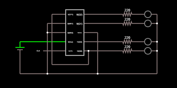
Posting how I connected the circuit. I used Falstad - Hope it's okay..

Circuit

Circuit

EDIT2:

I built the clock as per Ben Eater's instructions from YT. Schematics below

Clock Schematics

\$\endgroup\$
8
  • \$\begingroup\$ You need to post a schematic circuit diagram of the actual circuit including signal sources and power supplies. \$\endgroup\$
    – Andy aka
    Commented Apr 6, 2020 at 11:58
  • \$\begingroup\$ And tell us if this is a simulation or some actual hardware you've built and are testing. \$\endgroup\$
    – SteveSh
    Commented Apr 6, 2020 at 12:00
  • \$\begingroup\$ this is actual circuit. I don't have a diagram but I can try to draw it somewhere...I use 5v power supply from USB port using USB-C cable that I cut and connected to breadboard \$\endgroup\$
    – aberforth
    Commented Apr 6, 2020 at 12:02
  • \$\begingroup\$ Where is your clock coming from? If a push-button, then you're probably getting a bunch of edges due to contact bounce, which will manifest as all outputs doing something. Buffer your button with an RC and schmidt trigger to give single edges for single pushes, or make a low speed oscillator so that it just sits there and counts slow enough to see what's happening \$\endgroup\$
    – Neil_UK
    Commented Apr 6, 2020 at 12:23
  • \$\begingroup\$ I don't see any resistor on the board. How have you connected the LEDs to the outputs? \$\endgroup\$ Commented Apr 6, 2020 at 12:46

2 Answers 2

15
\$\begingroup\$

I see two issues:

  1. No decoupling caps. Edit: Add decoupling caps (see comment). When ICs switch state they draw a pulse of current on the 5V. Your power wires have enough inductance to cause the 5V to momentarily dip to near zero. This causes the IC to lose it memory.

  2. No series resistors on your LEDs, although some LEDs have built-in resistors, so I can't be sure.

For more information, you need to draw a schematic, I can't see all the connections.

\$\endgroup\$
10
  • \$\begingroup\$ I added the 220Ohms resitors for each LED and they all flash at the same time on with the clock signal... \$\endgroup\$
    – aberforth
    Commented Apr 6, 2020 at 12:30
  • 1
    \$\begingroup\$ @aberforth ADD A SCHEMATIC \$\endgroup\$
    – Andy aka
    Commented Apr 6, 2020 at 12:32
  • 3
    \$\begingroup\$ @aberforth - adding decoupling caps was in my answer. \$\endgroup\$
    – Mattman944
    Commented Apr 6, 2020 at 14:46
  • 15
    \$\begingroup\$ @MichaelKaras - I looked at the video, saw two potential issues. I made an educated guess, I was right. \$\endgroup\$
    – Mattman944
    Commented Apr 6, 2020 at 14:49
  • 5
    \$\begingroup\$ @MichaelKaras a little grumpy during the lockdown or something? \$\endgroup\$
    – Passerby
    Commented Apr 11, 2020 at 20:35
0
\$\begingroup\$

From your diagram, you don't appear to have it correctly connected: you appear to have QC (8) connected to CKA (14) and feeding CKB (1). Datasheet says you should have CKB (1) connected to QA (12) and feed CKA (14).

enter image description here
From TI Datasheet

\$\endgroup\$
1
  • \$\begingroup\$ Sorry, I drew it incorrectly, corrected now \$\endgroup\$
    – aberforth
    Commented Apr 6, 2020 at 14:09

Your Answer

By clicking “Post Your Answer”, you agree to our terms of service and acknowledge you have read our privacy policy.

Not the answer you're looking for? Browse other questions tagged or ask your own question.