5
\$\begingroup\$

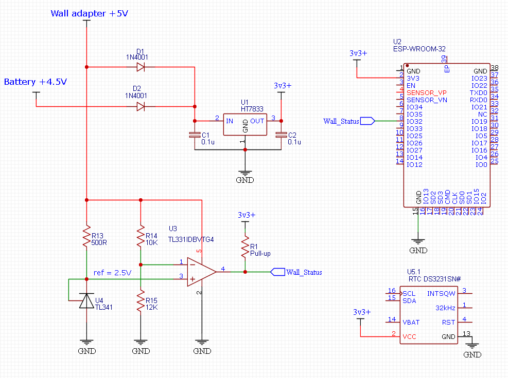
I’m trying to figure out if the following comparator circuit (TL331) would be reliable in the following application, or whether I would need to add anything, like hysteresis.

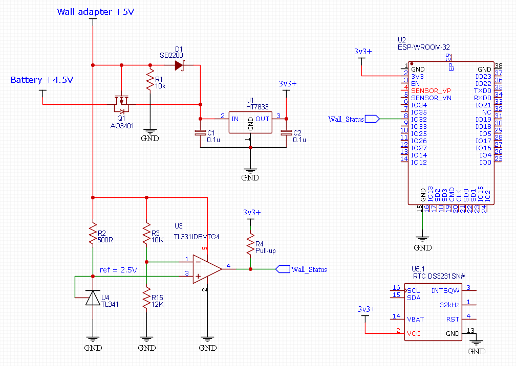
enter image description here

To explain the application, you have a microcontroller (ESP-32 in this case) powered by a 5 V wall adapter and it performs its normal operations ONLY when powered by the 5+ V wall adapter.

If the wall adapter turns off unexpectedly, then the microcontroller switches to the lower voltage battery power, backs up important variables to the internal flash storage and then enters into a deep sleep mode, where it consumes only a few microamps of current. A low quiescent current linear regulator ensures that there is a very low power draw on the battery. An external RTC can also be powered from the regulator.

I want to use a non-inverting comparator for this application, in order to send a digital signal to the MCU that the wall adapter is either ON, or OFF. I have created this using an open drain TL331 comparator and a 2.5 V fixed reference (using a TL341).

When the wall adapter voltage is above a voltage threshold of around 4.6 V (set by the voltage divider), then the open collector output turns LOW, and the MCU's input pin goes LOW.

When the wall voltage goes below the 4.6 V threshold, then the open collector output is disconnected, and the microcontroller registers a HIGH signal, through a pull-up resistor.

The non-inverting comparator and the 2.5 V reference are ONLY powered through the 5 V wall adapter, so as to prevent it from draining the battery when the microcontroller is in deep sleep. The 2 ORing diodes (D1 and D2) prevent the battery from ever powering the comparator.

An inverting comparator (with open collector output) would not work in this case, as you would need to send the MCU a LOW signal when the voltage is below 4.6 V, however, because the comparator is being powered by the wall adapter itself, the low signal will stop being sent once the wall adapter is completely switched off, as the comparator will be unpowered.

I’m wondering if such a comparator for this application would need hysteresis, or any other other circuitry to improve reliability? I’ve read that hysteresis is a bit trickier to implement for a non-inverting comparator however, so how could I do such a thing?

EDIT:

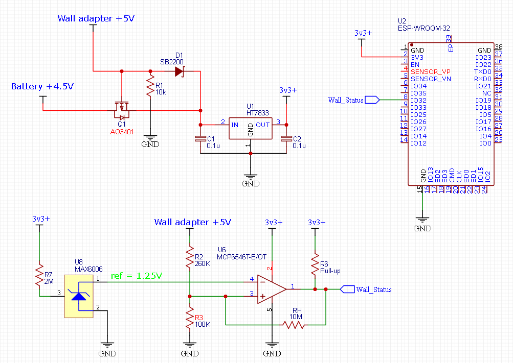
The original schematic uses diode's (1N4001) which could cause too much of a voltage drop for the 4.5 V battery. Therefore, I have changed the circuit to include a Schottky diode and a logic level P-channel mosfet, based on a PSU switching circuit I am familiar with. This will ensure only a very low voltage drop for the battery over it's entire voltage range. source of this circuit: https://electronics.stackexchange.com/a/418277/306786

enter image description here

UPDATE:

Based on Andyaka's suggestions, I think it would be better to go with a sub-microamp comparator (e.g. MCP6546) & reference (e.g. MAX6006), which are both continually powered by the 3.3 V low Q.I. regulator. The comparator can now be inverting, instead of non-inverting and hysteresis can be added with the resistor RH. Here is my basic thoughts for now, without doing any hysteresis calculations yet.

enter image description here

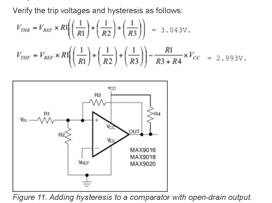
UPDATE 2: To calculate the hysteresis width for my latest schematic, I'm assuming that the below calculation would be suitable for my application, with a fixed reference voltage at the inverting input and an open drain comparator?

enter image description here

Source of calculations

\$\endgroup\$
10
  • 2
    \$\begingroup\$ You can't know without testing. Gradually increasing current and step change in current are totally different things and the converter inside will behave differently. A transmission is basically a step load change. It's important for your circuit's behaviour because, for example, if your circuit makes a transmission at power-up-from-adapter or at status-change-from-sleep-to-normal then it might ping pong between battery and adapter. I'd test it with 0 to 500 mA step change and see what happens to the output voltage. \$\endgroup\$ Commented Nov 22, 2022 at 9:48
  • 1
    \$\begingroup\$ Why can't you use a sub micro-amp comparator and voltage reference to de-complicate things? \$\endgroup\$
    – Andy aka
    Commented Nov 22, 2022 at 10:06
  • 1
    \$\begingroup\$ @Turboduinoz try this answer for other options: electronics.stackexchange.com/questions/610037/… \$\endgroup\$
    – Andy aka
    Commented Nov 22, 2022 at 12:08
  • 1
    \$\begingroup\$ Thanks @Andyaka. The MAX6006 1.25V reference looks suitable, as well as a sub-microamp open-drain comparator like MCP6546. I think I can now make an inverting comparator, with a hysteresis resistor, and power the comparator/reference continually through the low IQ 3.3v regulator \$\endgroup\$ Commented Nov 22, 2022 at 14:24
  • 1
    \$\begingroup\$ Scope is the best option normally, but you should be able to catch with an MCU as well. Assuming the recovery time to be around 1ms, you should take measurement in every half or a one third of a millisecond, at max, which means a sample rate of at least 3.3 kHz. The higher the better. Make sure to you filter out unwanted high-frequency components (above 33 kHz) for the sake of reliability and accuracy. \$\endgroup\$ Commented Nov 23, 2022 at 7:39

5 Answers 5

4
\$\begingroup\$

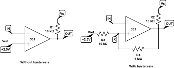
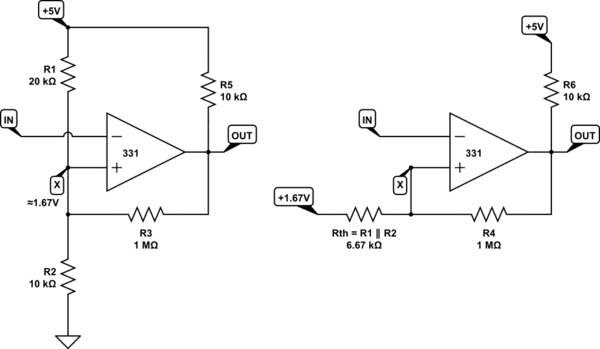
It's a little harder to implement positive feedback when the non-inverting input is held at a fixed potential, like 2.5V in you circuit, but it's not hard:

schematic

simulate this circuit – Schematic created using CircuitLab

You could say that by superposition, the potential at X, \$V_X\$, is produced by contributions from:

  1. \$V_{REF}\$ via R3, which is small compared to R4

  2. \$V_{OUT}\$ via R4, which is large compared to R3

Intuitively, and as a rough guide, any contribution to \$V_X\$ from the output \$V_{OUT}\$ is going to be about 1% (the ratio of resistances R3 and R4) of the magnitude of influence from \$V_{REF}\$. This means that a large output swing will result in a very small, 1% or so, fluctuation at X, which is the "hysteresis" you seek.

Of course you can calculate the exact thresholds levels algebraically, but in an application like this, a ballpark figure is probably all you need.

Most comparators have a tiny bit of hysteresis (of the order of 1mV) built in, but if the power supplies in your application fluctuate more than that, you could see your comparator output flapping around as the supply wobbles. That's likely when using a "wall-wart" adapter.

I think hysteresis here would be good thing, perhaps 0.1V, or even more. How much depends on the variability of the voltage sources involved.

If the comparator output swings from 0V to 5V, and you want 0.1V of hysteresis, you are aiming for feedback to modulate the non-inverting input potential by 2% of 5V. A good starting value for R4 above would be 500kΩ, for a ratio of R3:R4=1:50, or 2%.

If ever you derive the potential at the non-inverting input (the one you must modulate to implement positive feedback, hysteresis) using a resistor potential divider, the solution is even simpler. Because the output of the potential divider has a source impedance resulting from the use of resistances, that "reference signal" has a source impedance, whose value is the thevenin equivalent resistance of the pair:

schematic

simulate this circuit

In this configuration you get a good idea of the influence of the output at at X as you did before, by comparing Rth and R4. About 0.7% of the output change will appear at X in this example.

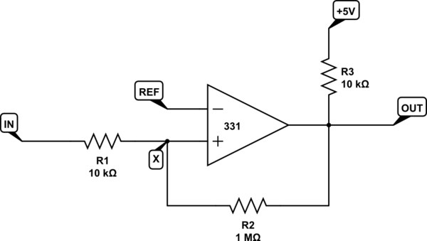
When it's the inverting input which is held at some reference potential, then positive feedback must modulate the actual input signal being compared, but the same principle applies:

schematic

simulate this circuit

The main consideration here is that the input impedance is now the sum of R1 and R2, which may or may not be a problem. However, the same idea is being employed, in that the input has a much larger influence on \$V_X\$ (about 100 times larger in this example) than the output, and that the relative contributions of both output and input will be roughly in the ratio of resistance R1 and R2.

\$\endgroup\$
4
  • \$\begingroup\$ The first example is really clicking with me, and I think I can apply those exact resistor value's to my application, thanks! \$\endgroup\$ Commented Nov 24, 2022 at 5:51
  • \$\begingroup\$ However, I'm not familiar with what this double vertical line "∥" does in the the equation used to calculate Rth. What does this do? thanks. \$\endgroup\$ Commented Nov 24, 2022 at 5:59
  • 1
    \$\begingroup\$ It means "in parallel with". You remember the formula for two resistors in parallel: \$\frac{1}{R_{TH}}=\frac{1}{R_1}+\frac{1}{R_2}\$ \$\endgroup\$ Commented Nov 24, 2022 at 9:40
  • \$\begingroup\$ All makes a lot of sense now :) There are also some 4.5v voltage supervisor IC's which have 0.1V of hysteresis built in, so 0.1V seems like a good width to aim for. \$\endgroup\$ Commented Nov 24, 2022 at 14:05
2
\$\begingroup\$

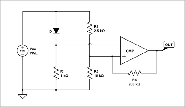
You can still use a simple 3-resistor non-inverting comparator with hysteresis if you flip the R1-D1 voltage divider and swap the op-amp inputs. Now the diode D (ordinary Si diode with VF = 0.7 V) is floating.

The networks D-R1 and R1-R2 can be thought as "half-bridges" forming a full bridge circuit supplied by a varying voltage Vcc. The trick is that the midpoint between D and R1 "moves" more vigorously than the midpoint between R2 and R3. So there is a moment when the two voltages "catch up" (become equal), the "bridge" is balanced and after a while, the comparator switches.

schematic

simulate this circuit – Schematic created using CircuitLab

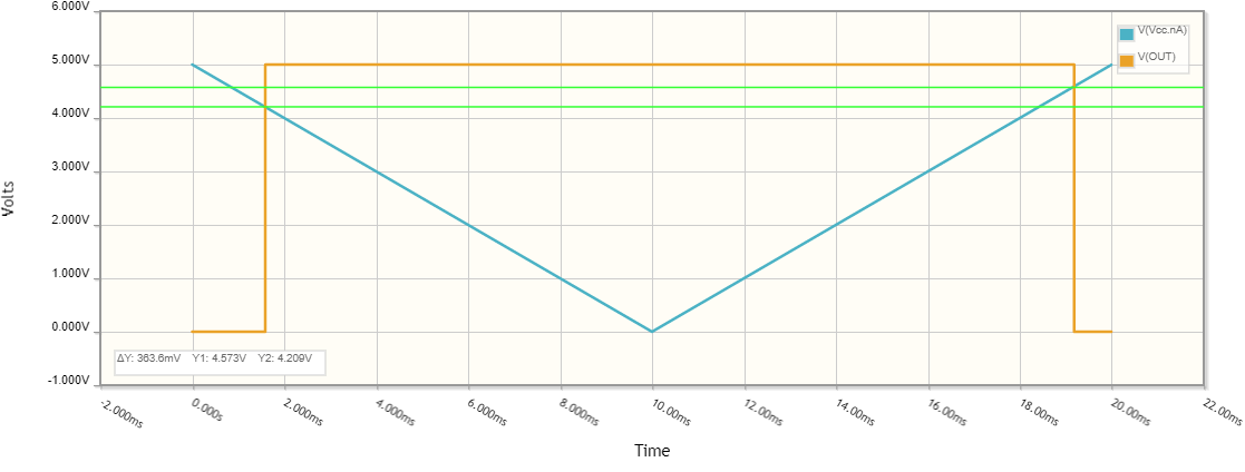
R4 introduces a small hysteresis by influencing the "soft" R2-R3 midpoint. You can simply think that R4 connects in parallel to R3 (when the output is low) or to R2 (when the output is high). With these resistance values, the hysteresis is about 300 mV. To see it, you need two Vin excursions - down (from 5 V to 0 V) and up (from 0 V to 5 V). That is why, I have used a more sophisticated "programmable" functional generator PWL (see the CircuitLab documentation).

Reset non-inverting comparator

\$\endgroup\$
1
\$\begingroup\$

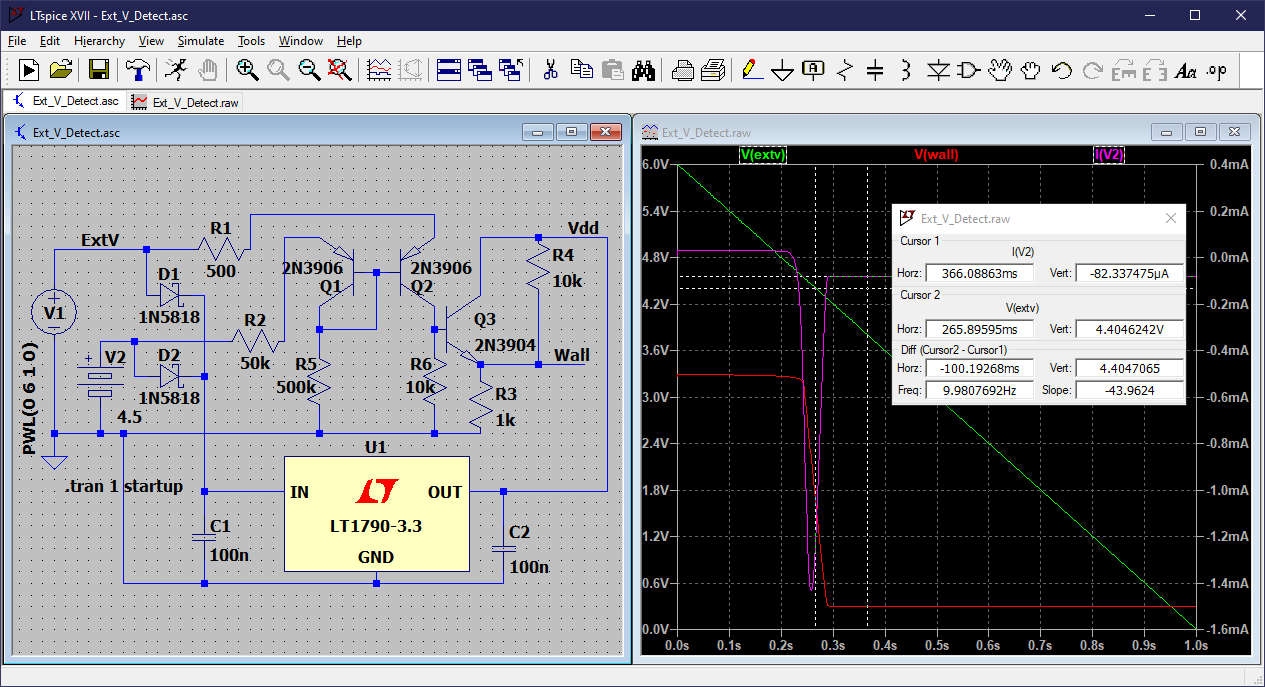
I figured out a way to do this using discrete components. It does not implement hysteresis at the crossover point, but I don't think it's really necessary, especially if the external source is disconnected, rather than gradually having lower voltage. This may or may not be practical or useful, and it may work a lot better in simulation than in real life, but I thought it would be an interesting challenge to come up with this alternative.

External Voltage_Detector

Note that when the external voltage is higher than the battery, it actually injects about 30 uA into the battery.

\$\endgroup\$
1
\$\begingroup\$

You seem to have gotten "here's how to add hysteresis" answers instead of "do I need hysteresis" answers.

You probably *don't need hysteresis" if you select your threshold voltage wisely, and if your control scheme can handle a noisy comparator transition. If it isn't dangerous, just try it without hysteresis.

\$\endgroup\$
0
\$\begingroup\$

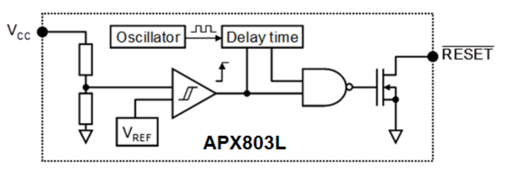
Personally I would use a voltage supervisor chip (aka "reset chip") like this one. It has everything you need: voltage reference, comparator with hysteresis, and a bit of delay to ensure the power supply is properly started. It's cheap, draws very low current, and it's only one part.

enter image description here

Basically, why spend a lot of time designing a circuit when one 40c part will do the job?

\$\endgroup\$
4
  • \$\begingroup\$ This is a good point, and I was originally going to use an voltage supervisor for this, however, the only problem that would occur is that when I reboot the program, such as for reuploading/debugging a sketch, I would want to do an initial check to see whether the MCU is being powered by either the wall or the battery... \$\endgroup\$ Commented Nov 24, 2022 at 5:41
  • \$\begingroup\$ ...If a high input is used to indicate that wall-adapter is present and a low signal is used to indicate that the battery is present, we have a problem, because the low signal of the supervisor is only active when the wall adapter is losing power, but once the wall adaper is completely off, the signal goes high again, because the open drain output switches off. \$\endgroup\$ Commented Nov 24, 2022 at 5:41
  • \$\begingroup\$ This wouldn't be a problem if the supervisor used an open drain "non-inverting comparator", as you would get a low signal when the wall adapter is present, and a high signal when both the wall adapter is losing power and when the wall adapter is completely off. I'm unsure if such parts exist though. \$\endgroup\$ Commented Nov 24, 2022 at 5:48
  • 1
    \$\begingroup\$ Yes, you're right, it would need separate pins for VCC and comparator input, I don't think supply supervisors exist in this configuration. \$\endgroup\$
    – bobflux
    Commented Nov 24, 2022 at 8:55

Your Answer

By clicking “Post Your Answer”, you agree to our terms of service and acknowledge you have read our privacy policy.

Not the answer you're looking for? Browse other questions tagged or ask your own question.