0
\$\begingroup\$

I've learned that an electric speed controller switches battery voltage on and off on each phase to drive a BLDC motor and uses PWM to control speed. Then I have some confusion.

The coils inside a BLDC motor themselves are large inductors, inductors always try to hold current. For one phase, when you switch on, the current can be gradually increased and eventually able to create enough torque, when you switch off, the coil will try to hold current and create arcing at where you cut the circuit, causing heating inside ESC.

Taking PWM into account, electric arc will be created every cycle. If the PWM frequency is too high, then there is not enough time to get enough current to create torque.

Is there some mechanism to allow motor coils to keep current, and how?

\$\endgroup\$

1 Answer 1

1
\$\begingroup\$

schematic

simulate this circuit – Schematic created using CircuitLab

The voltage source may not be able to sink current so the capacitors are necessary. The switches are either IGBTs, FETs or BJTs.

If all switches open while there is current in any pair of inductors it will pass through the capacitors via both rails.

Consider SW1, SW6 closed. L1,L3 will pass current. The switches are closed long enough so the inductive current in L2 is zero and L2 is generating back-emf.

The large green arrows show the L1,L3 current prior to SW6 opening and prior to SW4 closing. The red arrow shows that SW6 transitions from closed to open. The blue arrow shows that SW4 transitions from open to closed.

When that happens the current in L1,L3 is diverted through D6 as shown by the short green arrow. It then travels along the rail to SW1 and returns to L1 through SW1. Current builds through SW1,SW4 as shown by the yellow arrows.

The actions repeat in sequence as different pairs if switches operate. If an upper switch stays closed then the current is diverted to the positive rain. If a lower switch stays closed the the current is divertedti the lower rail.

Is there some mechanism to allow motor coils to keep current, and how?
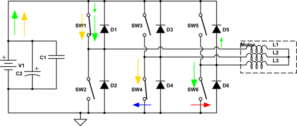
The mechanism is shown in the diagram.

\$\endgroup\$
5
  • \$\begingroup\$ If current is flowing from the motor into the ESC, it can flow through D1, D3 or D5. If current is flowing from the ESC into the motor, then it can flow through D2, D4 or D6. Both high side and low side diodes can act to prevent arcing depending on which way the current was flowing at the moment that the switch was turned off. \$\endgroup\$
    – user57037
    Commented Nov 27, 2022 at 1:45
  • \$\begingroup\$ Thanks @mkeith: I have made my meaning clearer. \$\endgroup\$
    – user319836
    Commented Nov 27, 2022 at 2:50
  • \$\begingroup\$ The switches are also frequently IGBTs. At least in industrial motor drivers; I don't know about the tiny ones used for hobby motors. \$\endgroup\$
    – Hearth
    Commented Nov 27, 2022 at 3:57
  • \$\begingroup\$ Thanks @Hearth. Of course they are . I updated, \$\endgroup\$
    – user319836
    Commented Nov 27, 2022 at 14:15
  • \$\begingroup\$ @Hearth typical ESCs for hobby use MOSFETs rather than IGBTs. \$\endgroup\$
    – user57037
    Commented Nov 28, 2022 at 1:25

Your Answer

By clicking “Post Your Answer”, you agree to our terms of service and acknowledge you have read our privacy policy.

Not the answer you're looking for? Browse other questions tagged or ask your own question.