1
\$\begingroup\$

I need to drive a some kind of pzt transducer with a triangular 6 Vpp voltage. The transducer is modeled as a 400 nF capacitor. I want to drive it with 10 kHz 3-9 V triangular voltage however my DAC device's output impedance is 50 Ω. So the circuit acts like a low-pass filter that has 8 kHz 3 dB frequency. As a result my triangular waveform gets distorted.

In the transducers datasheet it says I need to design a compensation network but I don't know how to do it. I figured I need to use a low output impedance, high slew-rate op-amp. I decided to use LT1818 but then I realized that it's output can’t go beyond 5 V.

My question is can I design a compensation network that retains the triangular network without using an op-amp? If not which op-amp should I use?

\$\endgroup\$
11
  • \$\begingroup\$ There are two approaches that come immediately to mind. (1) Design a low output impedance driver stage with maybe 10 Ohms max output impedance (or less.) That allows you to keep your DAC driver outputing a triangle wave. (2) Divide the fourier of the transfer function you have (50 Ohms output and 400 nF) into the fourier of the transfer function you want (triangle) and inverse fourier that to the time domain to get the drive curve to use. I've only 'some' idea where that will take you. But it's another approach. (It's used in IC lithography, as feature sizes have gone so small now.) \$\endgroup\$
    – jonk
    Commented Nov 28, 2022 at 8:53
  • \$\begingroup\$ @tobalt That is my own question in that 2nd case. However, as I also indicated, I've seen it used in IC lithography that takes the transfer function of the electron beam physics into account to create VERY SHARP images on the masks they get. What amazes me about that work I've seen is that the input to the litho system looks almost NOTHING at all like what they want to get on the IC mask. It's pretty shocking!! Spatial fourier (and possible filtering/masking in the fourier domain) is pretty impressive. I could recommend a good book on the topic. ;) \$\endgroup\$
    – jonk
    Commented Nov 28, 2022 at 9:01
  • 1
    \$\begingroup\$ Although I don't rely on my math skills I will try that. I also think I need to prepare a look-up table for the DAQ if I get a weird shape. \$\endgroup\$ Commented Nov 28, 2022 at 9:02
  • 1
    \$\begingroup\$ Best wishes! I think you have a suggestion now. You can experiment with the idea, easily. Or you can just do the math. It's not actually all that complicated and there are lots of tools out there (free) that will generate what you need. Sage and numpy, for example. \$\endgroup\$
    – jonk
    Commented Nov 28, 2022 at 9:08
  • \$\begingroup\$ Low impedance driver (op amp) must just be able to output ~ +/- 80 mA. \$\endgroup\$
    – Antonio51
    Commented Nov 28, 2022 at 9:51

2 Answers 2

2
\$\begingroup\$

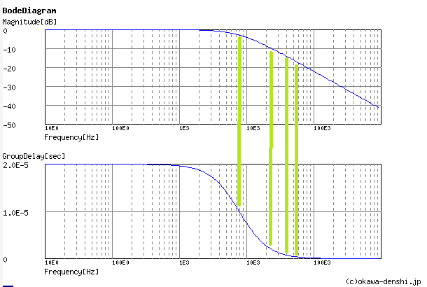
As indicated by @jonk, you can get around the RC induced time delay by offsetting each of the Fourier components according to their respective group delay.

The triangle contains many frequency components; you need to offset the lower frequency components more and more. And you must amplifiy the higher frequency components more and more. Here it is shown for the first four frequency components, schematically.

enter image description here

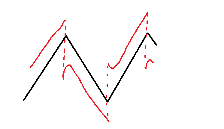
For a triangle, it will look intuitively as below. If you want the black trace, then write the red trace.

enter image description here

If you only want to work mildly above your RC filters -3 dB point, this is a feasible approach. However, note how the red trace has greater amplitude than the black one. This is the price you have to pay. As long as your DAC has amplitude headroom, you can make the resulting triangle as sharp and accurate as you like. But at some point, the amplitude correction for high frequencies will become too large to fit into the DAC output voltage range.

\$\endgroup\$
6
  • \$\begingroup\$ Thanks! You saved me from actually doing any work! \$\endgroup\$
    – jonk
    Commented Nov 28, 2022 at 9:05
  • 1
    \$\begingroup\$ @jonk Yeah, my comment earlier was dumb. You reminded me that the proximity correction used for masks, is exactly made to not be limited by the sharpness of the point spread function of the exposure (in certain cases). \$\endgroup\$
    – tobalt
    Commented Nov 28, 2022 at 9:07
  • \$\begingroup\$ The OP may yet have another degree of freedom. (And I'm just slinging mud against the wall to see what sticks.) They may add an inductor to generate a different transfer function. Since the DAC itself may have a limited slew rate (not accounted for, so far) doing so may either hurt or help with achieved output. Same process. Just yet another thing to consider playing with. \$\endgroup\$
    – jonk
    Commented Nov 28, 2022 at 9:17
  • 1
    \$\begingroup\$ Thanks. I'm now off to work :) \$\endgroup\$ Commented Nov 28, 2022 at 9:19
  • 1
    \$\begingroup\$ @MustafaTurhan Credit goes to jonk, though. I merely wrote this answer more to convince myself that my earlier (now deleted) comment was wrong. \$\endgroup\$
    – tobalt
    Commented Nov 28, 2022 at 9:21
0
\$\begingroup\$

Feed-forward compensation might be an attractive alternative to an op-amp buffer, provided that compensation is a simple wave-shape. The disadvantage of an opamp buffer having low output impedance is the significant power dissipation it must endure.

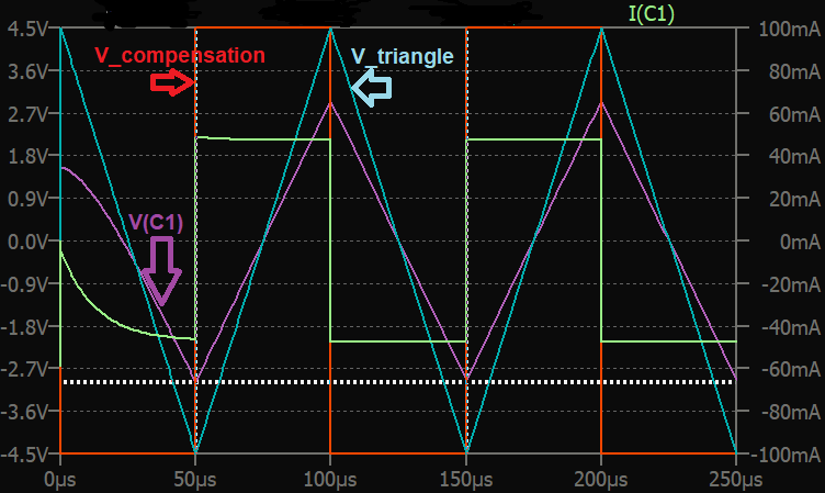
It is possible to use square wave compensation to compensate for the Rs=50 ohm output resistance of the triangle-waveform generator when driving a pure 400nF capacitance.

Disadvantages:

  • square=wave amplitude must track 1:1 with triangle-wave amplitude
  • phase of square-wave must track triangle-wave.

LTspice schematic square-wave compensating R_source of triangle waveform LTspice transient waveform  - compensation by square wave Ensuring that square-wave transitions track with triangle wave transitions may not be a difficult task. (Peaks of triangle wave correspond to square-waveform edges).
If the triangle wave is microcontroller-generated, it shouldn't be difficult to generate a square wave on a spare GPIO digital output pin.
If the triangle wave is generated from a Function generator, it is likely that a synchronous square wave is easily available, either on a front-panel output, or from an internal node (many function generators are fundamentally a triangle waveform from which sine and square are derived).

\$\endgroup\$
1
  • \$\begingroup\$ Thank you so much for yor efforts. We are using TiePie Handyscope. I need to ask my coworker for the synchronization part. \$\endgroup\$ Commented Nov 28, 2022 at 20:41

Your Answer

By clicking “Post Your Answer”, you agree to our terms of service and acknowledge you have read our privacy policy.

Not the answer you're looking for? Browse other questions tagged or ask your own question.