0
\$\begingroup\$

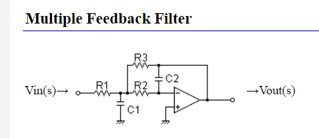
I'm trying to implement a low-pass filter using this circuit configuration:

enter image description here

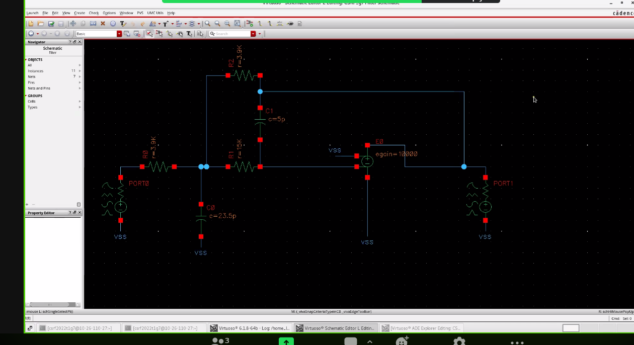
I first tried implementing in Cadence using an ideal op-amp:

enter image description here

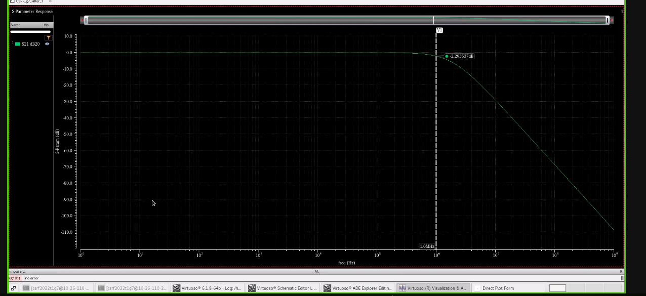
At 1 MHz I already have around -2.29 dB, so it's working as intended.

enter image description here

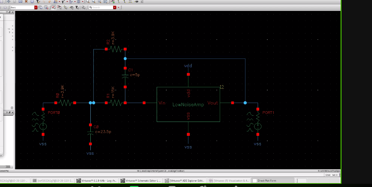
Then U replaced that ideal op-amp with a LNA that I made:

enter image description here

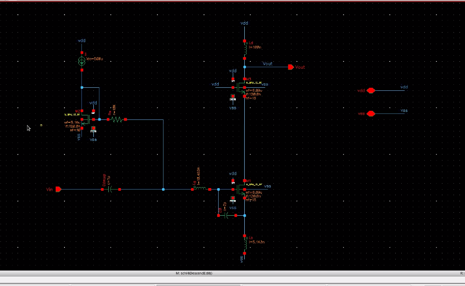
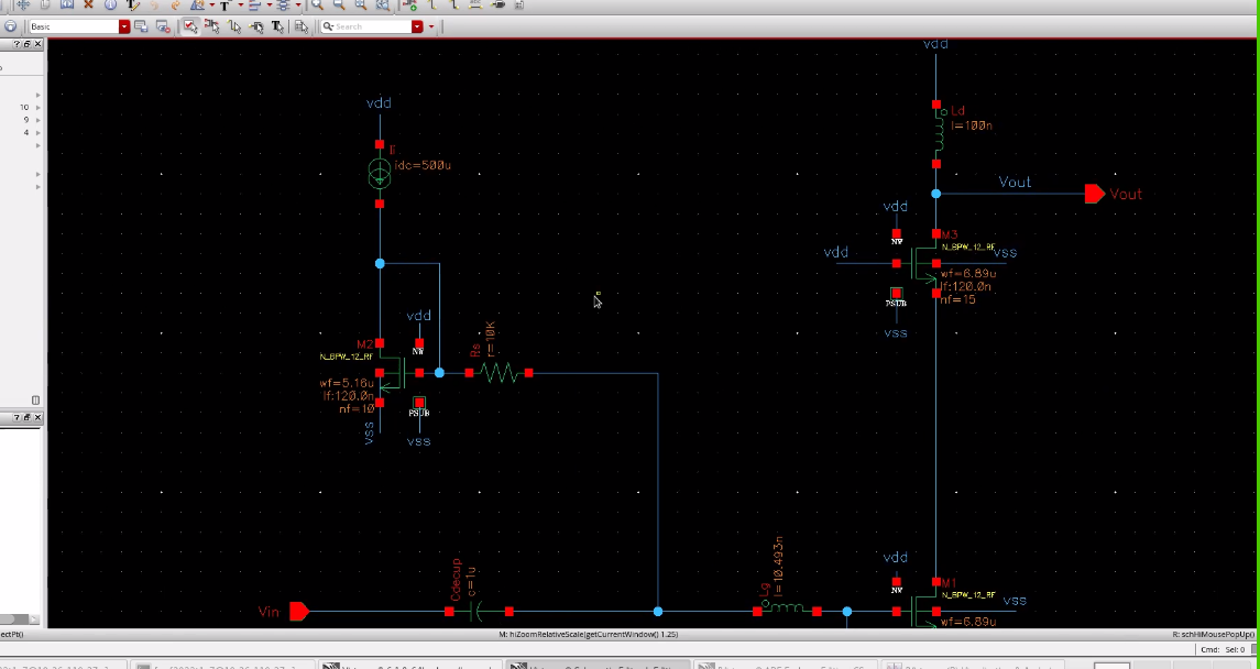
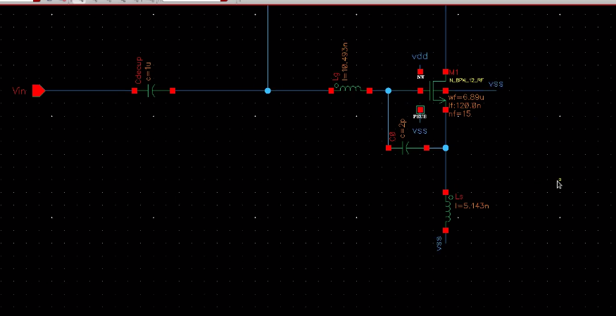
Here's what's inside the LNA:

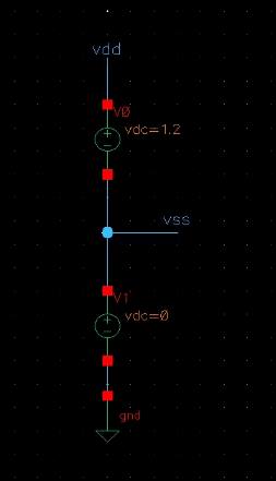
enter image description here

enter image description here

enter image description here

enter image description here

enter image description here

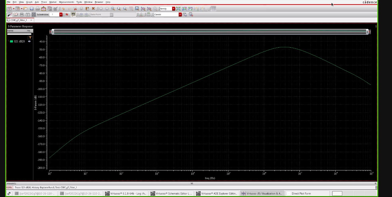
The frequency response doesn't make any sense. I want a response close to the ideal case.

enter image description here

Why does this happen?

\$\endgroup\$
0

1 Answer 1

4
\$\begingroup\$

You have a 1uF decoupling capacitor at the input of your LNA. That's why you see a bandpass behavior.

This produces a zero that, in turn, produces a high pass response. Therefore, you have made an amplifier that doesn't let DC through, so your full response has more of a bandpass behavior.

\$\endgroup\$

Your Answer

By clicking “Post Your Answer”, you agree to our terms of service and acknowledge you have read our privacy policy.

Not the answer you're looking for? Browse other questions tagged or ask your own question.