3
\$\begingroup\$

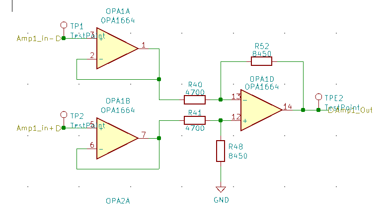
I have a basic circuit consisting of two buffers and one differential amplifier (kind of a instrumentation amplifier) .

It is powered by +5V and -5V (dual supply).

Amplifier circuit

When I turn on the power I get a ~3.6V at input of these op amps. I've tried to disconnect the feedback just to have an other point of view and is still the same.

Measure at TP1 : 3.6V

Measure at TP2 : 3.6V

Measure at TPE2 : 4.6V

Any clue about why I'm getting those voltages at the input when I only power them? I don't even connect a signal

UPDATE

I've connected signal to the input of the buffer and now the DC voltage at the inputs is gone, as well as the output. I've could see the signal. As well, I noticed that measuring with oscilloscope gives me 1.6V and with multimeter those 3.6V that I've mentioned. I'm wondering now, how could i solve the problem of the DC voltage at the output when is not signal connected to the op amp ? Could I use a pull down resistor ? and if yes, should be greater than the input impedance of the op amp right ? Thanks a lot for your help !

\$\endgroup\$
5
  • \$\begingroup\$ Why am I getting that voltage at the inputs (and the output) of each op amp ? They have negative feedback, and no signal connected to their inputs \$\endgroup\$
    – Dogo
    Commented Jan 4, 2023 at 1:49
  • \$\begingroup\$ How are you measuring this voltages? Which instrumentation are you using? \$\endgroup\$ Commented Jan 4, 2023 at 2:00
  • \$\begingroup\$ I've used a multimeter and also a oscilloscope. All measures referenced to ground \$\endgroup\$
    – Dogo
    Commented Jan 4, 2023 at 2:08
  • 3
    \$\begingroup\$ What voltages are you expecting to measure at those points, and why? \$\endgroup\$
    – brhans
    Commented Jan 4, 2023 at 2:21
  • \$\begingroup\$ TPE2 should give ~0 with nothing on the inputs.. Did you maybe also probe TP1 while checking TPE2 ? That could cause the necessary 2V difference in the inputs... \$\endgroup\$
    – tobalt
    Commented Jan 4, 2023 at 16:33

3 Answers 3

3
\$\begingroup\$

This can be due to the ac coupling of the instrument, this cause an almost total insulation between BJT input and the ground, remember then if the input is not connected to anywhere you can't bias the bipolar input BJT.

When, even a big resistive load is connected between input and ground (also 1 MOhm) you will see immediately your input voltage goes to zero thanks to the small bias current flowing throw the base.

Try to check the coupling method of your instrument, also the probes and try to avoid capacitive coupling

\$\endgroup\$
8
  • \$\begingroup\$ Thanks ! I will try to change the coupling method of the oscilloscope. It is still weird that the output went to almost Vdd \$\endgroup\$
    – Dogo
    Commented Jan 4, 2023 at 2:24
  • \$\begingroup\$ Ensure first you’re measuring correctly on the inputs, try to bias them with a high impedance pull-up/pull-down network. Then the output is directly related to the feedback and the signal \$\endgroup\$ Commented Jan 4, 2023 at 2:28
  • 1
    \$\begingroup\$ This is incorrect - the amplifier is bipolar. A resistor at the input will correct the problem but not as you have explained. \$\endgroup\$ Commented Jan 4, 2023 at 15:22
  • \$\begingroup\$ I didn't check the opamp datasheet, thank you for the hint \$\endgroup\$ Commented Jan 4, 2023 at 15:35
  • \$\begingroup\$ There is no indication that the input were AC coupled in the schematic or the OPs text. So -1 \$\endgroup\$
    – tobalt
    Commented Jan 4, 2023 at 16:20
7
\$\begingroup\$

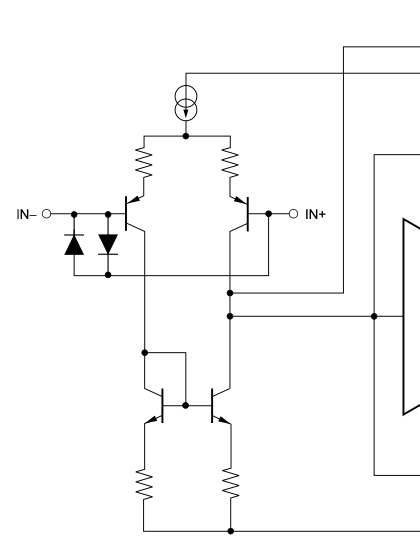
The OPA1664 (datasheet) is a bipolar amplifier with an input stage based on PNP transistors. It has an input bias current of about 600nA.

Since you do not have it connected to anything other than the meter that bias current will flow into the meter causing it to indicate the voltage you see.

Your circuit will not operate correctly unless you provide a path to a suitable bias voltage, such as ground. That may be provided by a resistor or the previous stage

Input stage

enter image description here

\$\endgroup\$
1
  • \$\begingroup\$ Thank you for your reply. Could this also explain the output voltage measured at the output pin of the amp ? \$\endgroup\$
    – Dogo
    Commented Jan 4, 2023 at 2:22
6
\$\begingroup\$

I don't even connect a signal

That's the problem. The behavior of an op-amp with open inputs is generally considered unspecified. The op-amp can do whatever - it solely depends on the details of its design and of the semiconductor process used.

The solution is simple: do not expect op-amps with floating inputs to do anything particular. They will do something, and what you see is what they do. They are "free" to do anything (within bounds of natural laws, of course). Accept what they do.

Then connect the inputs and move on :)

I get a ~3.6V at input of these op amps.

You're connecting the 10MΩ DC impedance, along with parasitic capacitances to mains, of the voltmeter, across a very high impedance input (much higher than 10MΩ). The op-amps will do their best at "buffering" this rather poorly controlled input signal, which may even be outside of the supply voltage limits and is very likely to be turning on the input protection diodes inside the op-amps.

Measuring the voltage at the input of the op-amp requires that:

  1. The input actually is driven by something else.

  2. The impedance of the measuring instrument is much higher than the driving impedance, all the way from DC to the end of the bandwidth of interest.

If the op-amp is driven by high impedance sources, e.g. 1MΩ, you'll need another op-amp to buffer this input voltage to measure it using a regular voltmeter, or you'd need to use a FET preamplifier - and the measurement techniques that entails.

\$\endgroup\$

Your Answer

By clicking “Post Your Answer”, you agree to our terms of service and acknowledge you have read our privacy policy.

Not the answer you're looking for? Browse other questions tagged or ask your own question.