2
\$\begingroup\$

For voltage sensing, we use a resistor divider and then we always feed that value of the resistor divider to an op-amp and then the op-amp output is fed to a microcontroller.

What exactly does the op-amp do in this case? Why can't we feed the output of the divider directly to the ADC of a microcontroller? What difference the does op-amp make here?

\$\endgroup\$

4 Answers 4

5
\$\begingroup\$

then we always feed that value of resistor divider to an op amp

Not always.

What exactly does the op amp do in this case?

To answer your question, let's first have a look at the divide-and-measure network:
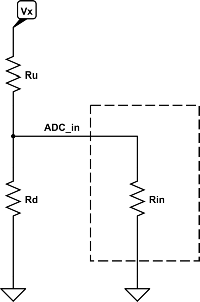
schematic

simulate this circuit – Schematic created using CircuitLab

When you connect the divider to the ADC input, the input impedance of the ADC (represented as Rin) will be a part of the divider. Depending on the MCU used, the value of Rin can be as high as hundreds of kiloohms, or even a few megaohms. You should always check the datasheets for that specific value/information.

In applications where the divider resistors (Ru and Rd) have to be very high due to strict consumption limitations, the input impedance of the ADC will simply "disturb" the divider and change the division ratio. For example, let's assume the input impedance of the ADC channel (Rin) is 500k, and the divider resistors, Ru and Rd, are 500k and 100k, respectively. The divider on its own is expected to have a division ratio of 100/(100+500) = 1/6. However, since the Rin is in parallel with Rd, makes the effective resistance 83k, and decreases the division ratio to 1/7. This will, of course, lead to false measurements.

Here, one may ask the possibility of removing Rd and using Rin on its own as the low-side resistor of the divider. Electrically, it's possible. However, Rin is not generally a fixed resistance i.e. it can vary with operational parameters such as clock frequency or sampling rate, or even chip to chip. So, Rin is a thing of which the effect should be compensated or kept as low as possible, for reliable operation.

To mitigate this, an op amp having very low input bias currents can be placed after the divider as a buffer (i.e. unity gain), and its output can be fed to the ADC because the op amp's output impedance is low enough not to interact with the input impedance of the ADC:
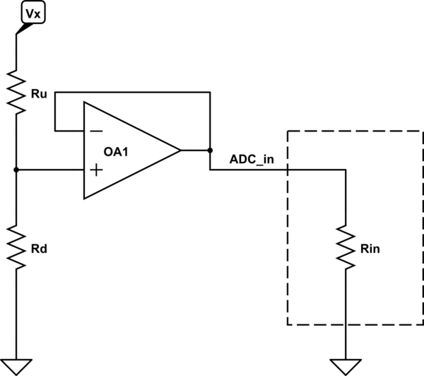
schematic

simulate this circuit

So,

Why we can't feed output of divider directly to ADC of micro controller?

We can, if the divider resistors can be kept low enough. Generally, a few tens of kiloohms for Ru and Rd doesn't bring any need of an op amp. For the same example above, if the divider resistors were 50k and 10k instead of 500k and 100k, the net division ratio would be 1/6.1 which is only 2% less than 1/6. Depending on the accuracy needs, op amp may further decrease the shift.

\$\endgroup\$
7
  • \$\begingroup\$ Thanks for explaination. what exactly is Rin here? \$\endgroup\$
    – Alison
    Commented Feb 14, 2023 at 9:44
  • \$\begingroup\$ @Alison check the updated answer. It's basically the input impedance of the ADC channel. \$\endgroup\$ Commented Feb 14, 2023 at 9:48
  • 2
    \$\begingroup\$ I can't be bothered to add an independent answer here, but the question arises, what about simply deleting Rd and using Ru+Rin as the divider? The answer is of course the uncertainty in the value of Rin, which may vary with clock rate or fabrication batch, or be too high to make a leakage-current-free divider with. Would you like at add another paragraph? \$\endgroup\$
    – Neil_UK
    Commented Feb 14, 2023 at 10:46
  • \$\begingroup\$ @Neil_UK good point. Adding... \$\endgroup\$ Commented Feb 14, 2023 at 11:31
  • \$\begingroup\$ @Neil_UK also, not including Rd would potentially violate max voltage ratings of the uC - the reason why we use voltage divider in the first place; especially when uC I/O is configured as floating, ADC (or MCU) is off, etc. \$\endgroup\$
    – Marandil
    Commented Feb 14, 2023 at 22:32
2
\$\begingroup\$

A resistor divider is a special case of KCL where current flows down from node 1 to node 2 through a resistor, and then all of that current flows from node 2 to node 3 through another resistor. Because the resistors share the same current, by Ohms law the ratio of voltages across them is equal to the ratio of their resistance. It is crucial to understand that if any current flows in or out of node 2, the resistors no longer have the same current and the voltage divider assumption no longer holds. Make sense so far?

Now let's take a look at what ADCs are doing. An ADC is a sample-hold circuit followed by a quantizer. Other pieces are involved depending on type of ADC but these are the two main things. The sample-hold component involves charging a capacitor by connecting it to the input until they reach the same voltage (sample), then disconnecting it so the capacitor holds that voltage (hold). Here it can be quantized, and the capacitor is discharged so it can again repeat the process.

Charging a capacitor requires, well, charge. A flow of charge is current. Charging and discharging a capacitor repeatedly at a fixed frequency draws a steady current. That's what's happening at the ADC input. If you connect the ADC input to the resistor divider, we break the divider.

What an op-amp does is act as a buffer. It negotiates a deal between the power supply, ADC, and resistors. The ADC wants the resistor voltage but it needs current. The resistor doesn't want to give current because that will ruin it's voltage. So what the op-amp does is it sees the resistor voltage, and tells the power supply to provide the current needed to fill up the ADC's capacitor until it reaches that voltage. Once it reaches that voltage the op-amp shuts off the current. The op-amp is a buffer for the divider, and a driver for the ADC.

\$\endgroup\$
1
  • 1
    \$\begingroup\$ Impressive explanation... Yes, this is how circuits should be explained to students so that they understand the principles on which they are built and then many times see them in all possible implementations... and not give them banal textbook truths. Indeed, the trick in an op-amp buffer is that the op-amp only "looks without touching" the resistor's voltage and creates a powerful "copy" of it using the power supply. Thus the current to the load (ADC) is taken from the power supply and not from the voltage divider. And all this is done using the ubiquitous negative feedback principle... \$\endgroup\$ Commented Feb 14, 2023 at 23:47
1
\$\begingroup\$

It's a buffer. It has voltage gain of 1, but very high input impedance (so does not load the voltage divider) and very low output impedance (so will not be affected by input impedance of the converter).

You have to check the datasheet of the ADC. Some already have this built in. Some have a lowish input impedance, perhaps 5-10k, and hence they will seriously load a typical voltage divider (and thus change the reference voltage).

\$\endgroup\$
1
\$\begingroup\$

The behavior of microcontroller analog inputs can't usually be modeled as a simple parallel impedance. Instead, the act of taking an ADC reading may be modeled as connecting a capacitor to the input at the moment the reading is taken, whose initial charge state may or may not be consistent between readings. I've seen some controllers where the initial charge state would always be zero, some where it would be roughly equal to the previous reading (whether on the same channel or some other channel), and some where the charge state would be sometimes high and sometimes low, chosen seemingly arbitrarily.

If an ADC input would act consistently like a moderately-high-value resistance to ground, that could be compensated for while using a simple voltage divider. Given the unpredictable nature of the capacitance and its initial charge state, however, getting accurate readings requires having circuitry on the input that can quickly charge or discharge the input capacitance to the right voltage.

A capacitor that is about 100 times as large as the input capacitance may suffice if one wants readings accurate to about 1%, but making the capacitance large will cause the circuit's input response to be sluggish. If one wants 0.1% accuracy, that would require a capacitor 1,000 times as large as the input capacitance, which would make input response even more sluggish.

An op amp may be a little bit more expensive, but would have the advantage of being much more responsive, and would represent an "it just works" solution to the problem. If one uses a large external capacitor to minimize the disturbance from connecting the chip's internal capacitance, one must worry about whether future versions of the chip might have a larger input capacitor, thus disturbing the measured voltage more. If one uses an op amp, such issues go away.

\$\endgroup\$
2
  • \$\begingroup\$ The behavior of microcontroller analog inputs can't usually be modeled as a simple parallel impedance. not "simple" but still a parallel, variable impedance. Consider the sample-and-hold operation again: while the switch is off the reverse-biased clamping diode will be in parallel, and it's leakage represents a parallel impedance. And while the switch is on, the leakage of clamping diode, the parallel resistance of the capacitor, and the input impedance of the sampling circuit come into play. Of course, won't be a fixed value but a frequency- and design-dependent parallel impedance. \$\endgroup\$ Commented Feb 15, 2023 at 8:27
  • \$\begingroup\$ @RohatKılıç: If one feeds an ADC from a resistor divider and parallel capacitor, and the ADC's sampling capacitor state is random, the amount of noise injected by that random state will be reach a local maximum when there is a moderate amount of external capacitance. If the sampling rate is constant, one might be able to design an RLC network which, given the signal and a random noise input, would behave in a manner consistent with the ADC input, but the behavior would be frequency dependent in a way that cannot be modeled by a single complex (RLC) impedance. \$\endgroup\$
    – supercat
    Commented Feb 15, 2023 at 15:53

Your Answer

By clicking “Post Your Answer”, you agree to our terms of service and acknowledge you have read our privacy policy.

Not the answer you're looking for? Browse other questions tagged or ask your own question.