4
\$\begingroup\$

I have recently integrated an ideal diode circuit based on the TPS2419D chip from TI.

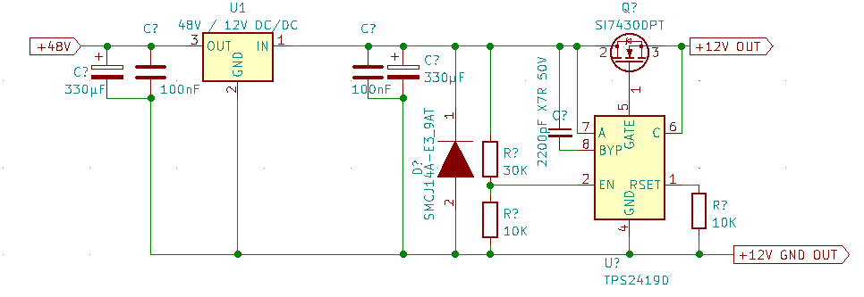
The schematic is the following:

TPS2419D circuit

When I apply 48 V to the input of the DC/DC, I do get 12 V at the output of the DC/DC, but almost nothing at the output of the ideal diode.

I've probed the values in this phase and they are like this :

  • pin1 (RSET): 0 V
  • pin2 (EN): 3.017 V
  • pin3: 0 V
  • pin4 (GND): 0 V
  • pin5 (GATE): 0 V
  • pin6 (C): 0.1 V
  • pin7 (A): 12 V
  • pin8 (BYP): 10.88 V

As I've discovered (not on purpose), if I shunt pin 6 & pin 7 briefly, the circuit will "wake-up" and I get 12 V at the output.

I've put a mild load (0.5 A) and it seems to work, but as soon as I unplug it the circuit has to be "woken up" again.

I'm a bit lost so any leads will be appreciated.


ADDENDUM (15/03/23) :

After @Tom-Carpenter pointed out that my FET was the wrong way around, I managed to cobble a test circuit together.

However, the circuit remains unfunctional.

  1. the FET might have been damaged in the rework process but I doubt it.
  2. I now obviously get a voltage at the output of the MOSFET all the time at the +12 V out, but it's more than likely the body diode conducting since I get a steep voltage drop (11.4 V with 12.05 V before the FET) even at very low current. Also, the gate voltage is only 12 V (referenced to ground) so Vgs is not where it should it be, correct?
  3. The voltage at pin 8 (BYP) is 22 V so it seems like the bootstrap/charge-pump is working, but why doesn't it drive the gate?
  4. Last but not least: when I use it as a blocking diode (U_post_mosfet > U_pre_mosfet), the MOSFET heats up quite quickly and I get a rapid clicking noise (2 Hz maybe), not exactly the behaviour I expected.
\$\endgroup\$
4
  • \$\begingroup\$ if I shunt briefly the pin 6 & pin 7, the circuit will "wake-up" ... what makes you think that the circuit wakes up? ... connecting pin 6 to pin 7 bypasses the MOSFET, therefore the circuit is bypassed \$\endgroup\$
    – jsotola
    Commented Mar 15, 2023 at 0:19
  • \$\begingroup\$ I only shunt it briefly and then the 12V stays at the output until I remove the power. \$\endgroup\$ Commented Mar 15, 2023 at 0:23
  • \$\begingroup\$ Have you connected pin 3 (RSVD) of the IC to ground? \$\endgroup\$ Commented Mar 15, 2023 at 9:43
  • \$\begingroup\$ Yes pin 3 is connected to GND \$\endgroup\$ Commented Mar 15, 2023 at 9:44

1 Answer 1

7
\$\begingroup\$

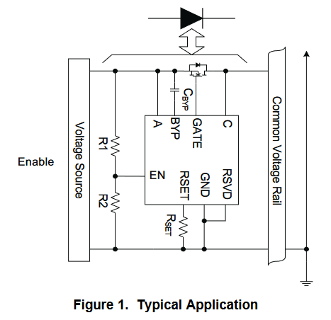
As can be seen from the typical application schematic in the datasheet, your MOSFET is wired up backwards:

Application circuit

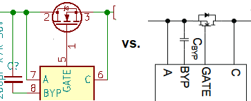
The source should go to the input (voltage source), and the drain to the output. However, you have connected the source to the output.

Schematic Difference

As to why it starts working if you briefly short the A-C pins together, this is because the C pin is what is actually powering the ideal diode controller.

C is both the cathode voltage sense and the bias supply for the gate-drive charge pump and other internal circuits. This pin must be connected a source that is 3 V or greater when the external MOSFET is to be turned on

With the MOSFET the correct way round, current can flow through the body diode from the input to the output, which in turn applies power to the C pin allowing the device to be turned on using the EN signal.

With the MOSFET reversed, the body diode now points the opposite way and so when the MOSFET is off, no power is applied to the C pin (you measure as 0.1 V showing this).

If you momentarily short out A to C, then you now have power applied to the C pin which allows the device to turn the MOSFET on. As the ideal diode is now in the on state, you are able to remove the short because the device remains powered through the MOSFET.

However, when turned on by this shunting method, your ideal diode is basically backwards and does not function correctly. When off, power can flow through the body diode in the wrong direction. When on, the MOSFET is not being controlled correctly.

\$\endgroup\$
4
  • \$\begingroup\$ Wow, I've missed this one... Thanks @Tom Carpenter. Though I don't understand why it still works when I "shunt 6&7... \$\endgroup\$ Commented Mar 15, 2023 at 0:10
  • 1
    \$\begingroup\$ @VoltsAndNuts With the MOSFET the correct way round, current can flow through the body diode from the input to the output, applying power to the C pin which is what powers the IC. With the MOSFET reversed, this doesn't happen so the IC stays turned off. When you short the pins out, this applies power to C and the IC can turn on and then stay on. \$\endgroup\$ Commented Mar 15, 2023 at 0:24
  • 1
    \$\begingroup\$ And even with the shunting, it only works in the sense that it conducts. It will not be able to block reverse current with the MOSFET wrong way around, because the body diode will let it through. \$\endgroup\$
    – jpa
    Commented Mar 15, 2023 at 7:55
  • \$\begingroup\$ @jpa, very true. \$\endgroup\$ Commented Mar 15, 2023 at 8:42

Your Answer

By clicking “Post Your Answer”, you agree to our terms of service and acknowledge you have read our privacy policy.

Not the answer you're looking for? Browse other questions tagged or ask your own question.