1
\$\begingroup\$

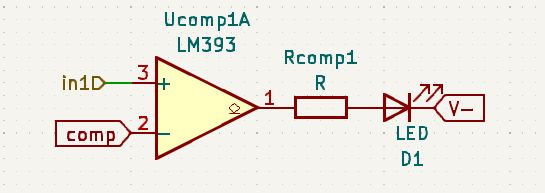
I want to design an audio mixer. The audio signal comes from an audio jack and is then buffered by an op amp. I want to have an LED that indicates whether the signal is close to saturation for this op amp.

I have a voltage divider that gives me the comp reference at 75% between V- and V+.

Will the following circuit work for my use case? Do I need to add a diode to act as a peak detector?

enter image description here

\$\endgroup\$
8
  • \$\begingroup\$ You should really show a full schematic, including power supply and audio input coupling capacitors (if any). Even so, the LM393 can only sink current, and cannot source current to the LED. Reverse the LED, and connect to V+ \$\endgroup\$
    – glen_geek
    Commented Apr 19, 2023 at 13:57
  • \$\begingroup\$ Mobile phone outputs are rated to typically drive a 32 ohm load such as a speaker driver directly. I wonder what is the purpose of buffering that low impedance with an op-amp. \$\endgroup\$
    – Justme
    Commented Apr 19, 2023 at 14:09
  • 1
    \$\begingroup\$ Think about an input signal of 76 %. The LED would be lighting for very short time intervals with a long gap between two pulses. You would see the LED light only in a very dark room. You need a retrigerable one shot to extend the pulses to about 20 ms. \$\endgroup\$
    – Uwe
    Commented Apr 19, 2023 at 14:23
  • \$\begingroup\$ @Justme , English isn't my mother tongue. I was referring to audio jack connector. There is no phone in my setup. \$\endgroup\$ Commented Apr 19, 2023 at 16:40
  • 1
    \$\begingroup\$ Yes, I would use a monostable multivibrator to extend the pulses for better visibility. \$\endgroup\$
    – Uwe
    Commented Apr 19, 2023 at 20:48

2 Answers 2

2
\$\begingroup\$

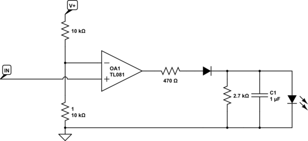
There are so many approaches to this. It seems that what you are looking for is a red LED which will warn you when the level is close to (presumably audible) clipping. This is a common requirement, the usual approach to this is to have the LED common at either 3dB or 6dB below the maximum output level. The usual approach is to use a comparitor which charges an RC circuit (this effectively works as a monostable as suggested by others but is a bit simpler). Ideally you would want to detect either negative or positive peaks, but many designs economise a bit by only looking at one peak.

LM393 is indeed a comparator (probably how you got to it) but as audio opamps like NE5532 and TL074 are typically plentiful in a mixer, you can just as well use one of those as a comparator, and keep your parts count down a bit.
schematic

simulate this circuit – Schematic created using CircuitLab

It's usual for such a circuit to have a fairly fast attack time (here I set a time constant of 0.5ms) but (as very short periods of clipping are inaudible) not too fast, and a longer release time to make clipping on short peaks visible. I didn't work the values through thoroughly, and in any case you usually end up tweaking the values manually as the LED you choose will itself affect discharge time. It's not super critical, you just want to make sure you see the peaks.

The series diode and RC network should do this well enough for most applications. Note that you might prefer a 5532 over an 072 for this, as it have better current drive.

\$\endgroup\$
1
  • \$\begingroup\$ Naïvely I would have thought that there exists some IC with delay that would normally cause an issue but which could be used here advantageously, but that seems not to be the case. \$\endgroup\$ Commented Oct 12, 2023 at 19:44
0
\$\begingroup\$

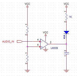
The LM339 has an open collector output so can’t drive its output high – you’d need to add a pullup resistor for that to work.

It would be better to take advantage of the LM339’s strong pulldown strength and have that turn on the LED. Connecting input to ‘-‘ input then cause the LED to come on when threshold is exceeded.

To keep the LED on for some persistence a capacitor can be added to the ouput. This will discharge immediately and only slowly charge through the LED resistor. This cap may have to be fairly large to get an acceptable persistence.

Note this circuit will only work if the audio input is swinging between 0 and VCC.

enter image description here

\$\endgroup\$
3
  • 1
    \$\begingroup\$ It only works if audio is between 0V and about 2V below VCC supply. But audio generally is biased to 0V and goes below 0V and above 0V. A typical modern line out would be 2Vrms or 5.6Vpp, going 2.8V negative and 2.8V positive. So this circuit alone won't be very good. \$\endgroup\$
    – Justme
    Commented Apr 19, 2023 at 19:02
  • \$\begingroup\$ To clarify - "The upper end of the common-mode voltage range is limited by VCC – 2V. However only one input needs to be in the valid common mode range, the other input can go up the maximum VCC level and the comparator provides a proper output state. Either or both inputs can go to maximum VCC level without damage." So keep reference (+ input) below VCC-2. But the audio_in does need to be biased (above 0). This is straightforward in a single-supply system but for bipolar supplies and signals the LM339 is not a great choice. \$\endgroup\$
    – td127
    Commented Apr 19, 2023 at 19:20
  • \$\begingroup\$ you will current limit the output stage of the 339 with this, because of the high discharge current of the cap, which needs to be fairly large to keep the LED on for any reasonable length of time. The chip will likely be OK but it could cause other problems like low level clicks in other sensitive parts of the circuit. A low value series resistor in series with the cap would be wise. \$\endgroup\$
    – danmcb
    Commented Oct 12, 2023 at 10:03

Your Answer

By clicking “Post Your Answer”, you agree to our terms of service and acknowledge you have read our privacy policy.

Not the answer you're looking for? Browse other questions tagged or ask your own question.