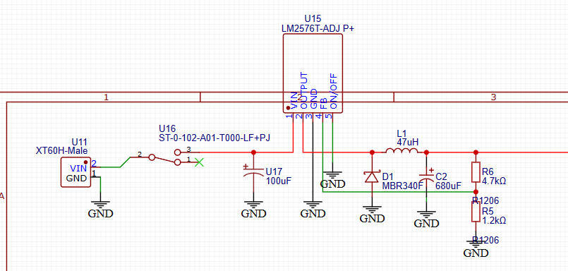
I am working with a LM2576T-ADJ that is taking as an input voltage a 2 cell Li-Po battery that in my application won't decrease below 8V and should output a voltage of approximately 6V to power a pair of Pololu Micrometal Gear Motors that will have a peak combined load of 3A.
I have followed the datasheet (https://www.ti.com/lit/ds/symlink/lm2576.pdf) and TI's Simple Switcher document (https://www.ti.com/lit/an/snva054c/snva054c.pdf?ts=1684356810650) to the best of my knowledge however when I assembled the circuit I got an output voltage of approximately 7.6V. My reading was taken with a multimeter as I don't have access to an oscilloscope and I am sure that the reading is somewhat correct as when I measure the voltage across the battery's leads I get 8V which corresponds to the voltage reading of a small Li-Po undervoltage module I have.
Below I have attached the manufacturer's schematic of the switching voltage regulator; the manufacturer's example layout for a PCB for the switching voltage regulator; my schematic for the switching voltage regulator circuit used in my project; and the layout of the components on my PCB.
In addition, the links to the components are: L1 D1 U17
Also this is a 2 layer PCB so the bottom layer (blue) is the GND layer that is a copper pour. I have identified the fact that the pins on the LM2576T-ADJ TO-220-5 are very close together which makes soldering hard and there might be a short however I did a continuity test using my multimeter and there were only small resistances between pins 3 and 5 which are both connected to ground.
Any help would be greatly appreciated as I want to get to the root cause of this issue as many projects I want to do in the future require high efficiency power supplies and I don't want to spend a lot of money on breakout boards with SMPS from the likes of Pololu.


