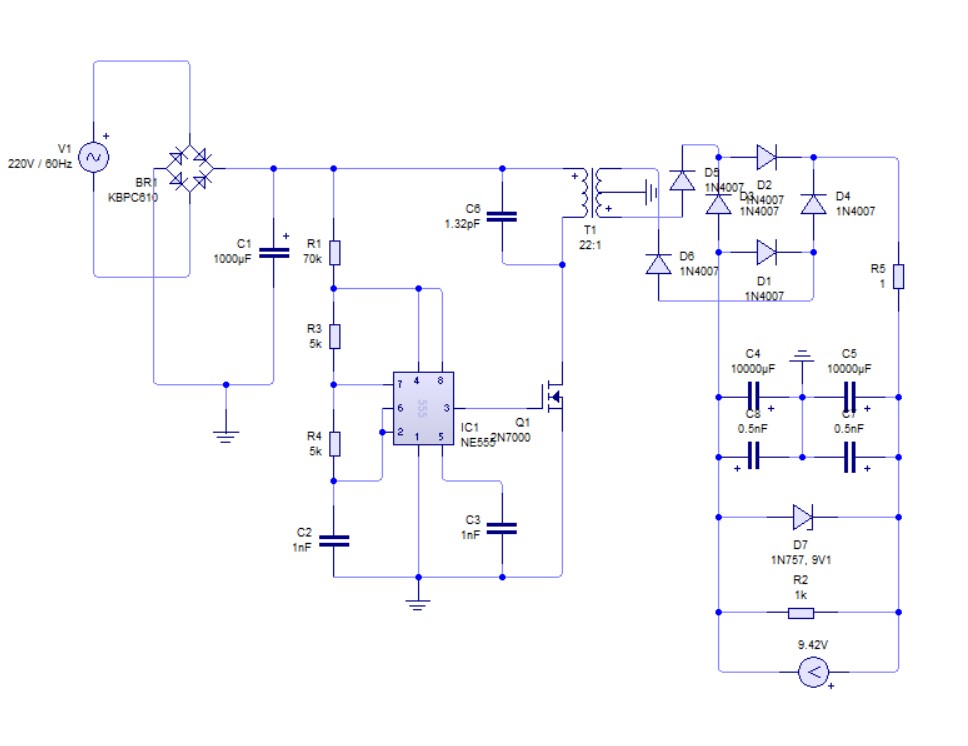
I'm working on a switched mode power supply that outputs 9 V in a simulation using a NE555 timer connected to the gate of my MOSFET and switching at 96 kHz frequency. Other components works just fine except the MOSFET which keeps on blowing because of gate-drain voltage exceeding 20 V. I tried putting resistors, diodes but still nothing. What should I do? What am I doing wrong?
-
\$\begingroup\$ What is the inductance of your primary? \$\endgroup\$– periblepsisCommented Sep 10, 2023 at 15:08
-
\$\begingroup\$ Is it really your gate-drain voltage that is exceeded at 20V? Or is it your gate-source voltage? AFAIK, a 2N7000 can sustain 60V across drain to source with gate-source voltage at 0. \$\endgroup\$– Math Keeps Me BusyCommented Sep 10, 2023 at 15:17
-
4\$\begingroup\$ This isn't a power supply, it's a smoke generator. Please use a proper controller like UC3842, and follow all application recommendations in the datasheet. \$\endgroup\$– Tim WilliamsCommented Sep 10, 2023 at 15:18
2 Answers
Why do my MOSFET keep blowing up saying the gate-drain voltage exceeds its rating?
You are rectifying and smoothing 220 volts. This produces a DC voltage of over 300 volts and, you are hoping to switching the primary of the transformer with a 2N7000 that is rated for 60 volts. This will always end in failure.
When the 2N7000 deactivates, the voltage at the drain would naturally rise above 400 volts and, that will destroy the MOSFET in an instant.
What should I do? What am I doing wrong?
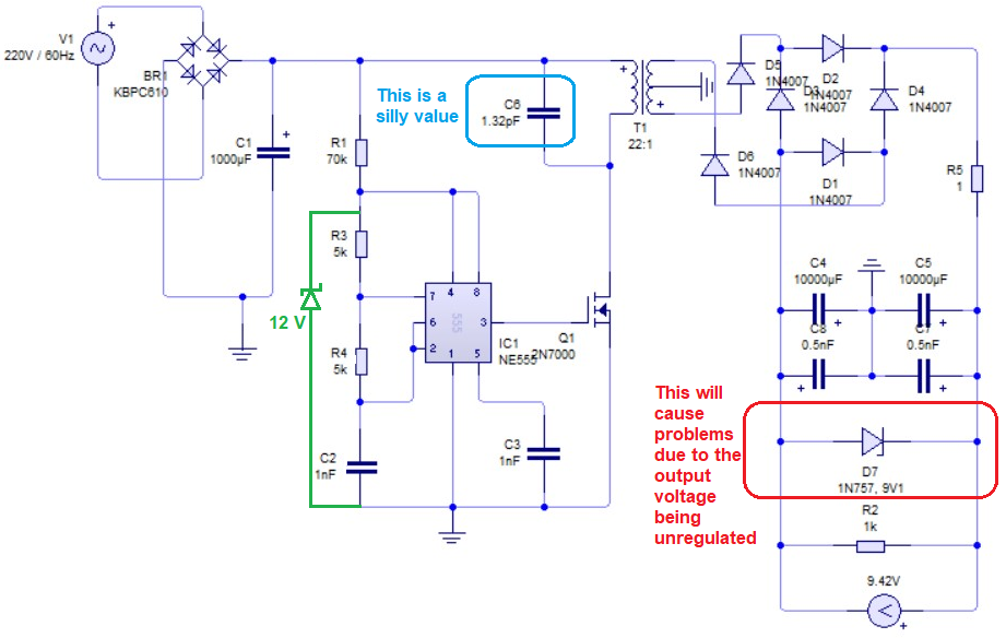
Pick a MOSFET with a voltage rating of more like 650 volts and use a diode-RC clamp circuit across the primary. In addition, your circuit is a flyback converter (due to D5 and D6) thus, adding a bridge rectifier on the output is really pointless. Use a fast diode for D5, ditch D6 and ditch the bridge rectifier formed by D1 to D4.
Neither can you produce a split output rail with this type of configuration without more secondary windings. There appears to be several other mistakes that I've summarised in the diagram below: -
The main one being that you need something like a 12 volt zener diode to regulate the supply to the 555 timer.
-
\$\begingroup\$ What limits the supply voltage to the 555? You have 6 diodes in the rectifier area. Remove D5,6. 1N4001 is very slow. It will burn up on a PWM. Use uF4001, or 4002. \$\endgroup\$– user338146Commented Sep 10, 2023 at 15:44
-
1\$\begingroup\$ @ronsimpson raise this comment to the OP and not me. Removing D5 and D6 is probably not a good idea. \$\endgroup\$– Andy akaCommented Sep 10, 2023 at 15:46
-
\$\begingroup\$ The phasing on the transformer suggests forward convertor, but I think the idea is flyback. \$\endgroup\$– user338146Commented Sep 10, 2023 at 18:31
-
\$\begingroup\$ It's a mess of an attempted design for sure @ronsimpson. But, I'm trying not to get too bogged down in solving the smaller problems i.e. the main question was about the MOSFET failing and, flyback or forward, the reason is the same. \$\endgroup\$– Andy akaCommented Sep 10, 2023 at 18:51
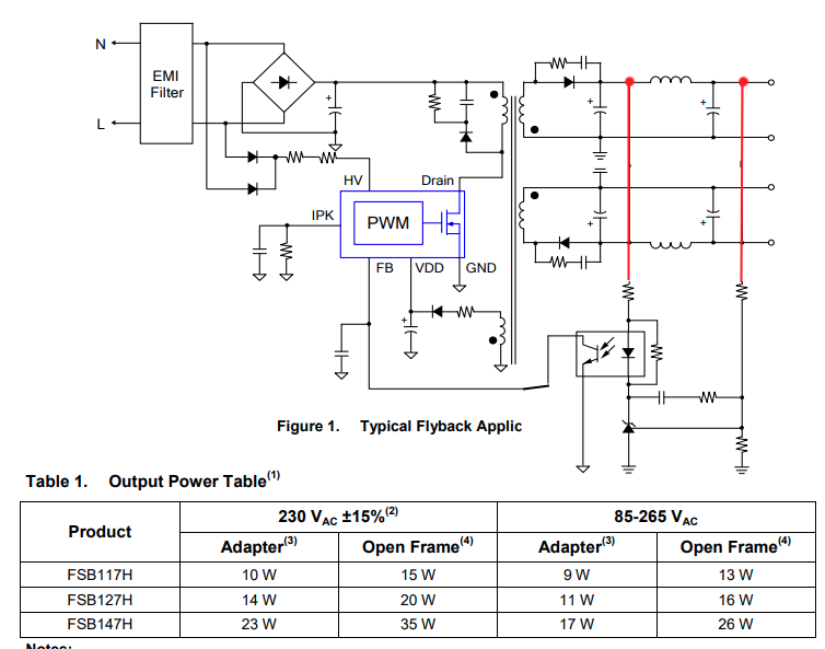
Picture from datasheet. OnSemi

The capacitors are wrong on the negative supply.
-
\$\begingroup\$ Did you edit Figure 1. Typical Flyback Application from the linked FSB117H datasheet to add a secondary winding for the negative supply? Not sure how the
FBfeedback pin is able to regulate both positive and negative supplies in that case. \$\endgroup\$ Commented Sep 10, 2023 at 19:16


