I designed a step down converter using WEBENCH. It takes 8-24V DC input and outputs 5V. The basic design works fine, but I learned from this question about why it died when I connected it to a 24V power supply that was already turned on.
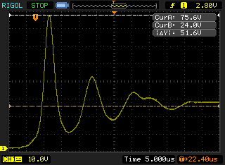
I did some experiments with the dead board. Here's an oscilloscope trace showing the max voltage when the 24V PSU is powered up and the input capacitors charge:
A peak of 75V, even for a few microseconds, is far above the 26V absolute maximum rating of the TPS51396A.
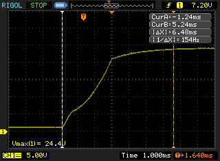
For comparison, here is the trace if the circuit is powered up with the cable connected (note different X and Y scale).
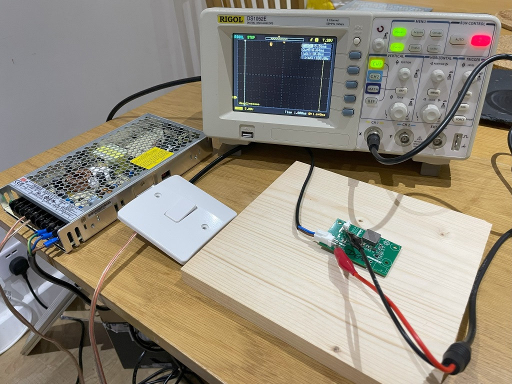
The test setup for these traces is shown below:
Instead of a probe I used crocodile clips - positive across the incoming supply and GND at the output (which is connected to the inner ground plane). The switch connects the output of the power supply to the input of the converter.
The application note referenced in this answer is useful. I avoided aluminium electrolytic capacitors because they are typically less robust (the PCB is not in a case), but could add one to a future revision of the board.
A TVS diode seems like a sensible choice but I am struggling to find a suitable option because the working voltage of 24V is very close to the 26V absolute maximum rating. A similar problem is described in this question, but in that case there is 12V between the working voltage and absolute maximum.
For future revisions I could add a general purpose diode for reverse polarity protection, which would give slightly wider voltage range due to the diode drop.
Is it possible to find a TVS that will clamp these excess voltages, or should I be looking for a different solution?


