0
\$\begingroup\$

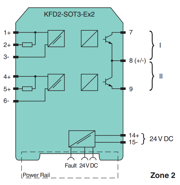
I am checking the datasheet of a Switch Amplifier (KFD2-SOT3-Ex2, see below), to isolate two parts of the circuit. I suppose the square blocks are relays, but what does the left one with the double bar mean?

For relays, I am used to seeing a rectangle with a bar that is connected to a switch with a dashed line; so I found this diagram not really clear.

Am I right to assume it is a relay?

Component diagram

\$\endgroup\$
0

1 Answer 1

1
\$\begingroup\$

It's not a relay but a two-channel switch amplifier with isolated barrier, used in 'Intrinsic Safety' applications.

'Intrinsic Safety' is an approach to the design of equipment intended for use in areas with a flammable or explosive environment. The idea is to reduce the available energy to a level where it is too low to cause ignition. That means preventing sparks and keeping temperatures low.

In such an environment the current in electrical switches and sensors (known as 'Namur' sensors) is to be limited to 1.2 mA (On) and 2.1 mA (Off).

The symbol depicts the galvanic isolation that separates the input, output and power supply circuits.

In simple terms the switch amplifier, intended for 'Intrinsic Safety' applications, is used to transfer digital signals from a hazardous area to a safe area.

\$\endgroup\$
7
  • 1
    \$\begingroup\$ @Andrew Morton - Thank you, Andrew. The double bar depicts the galvanic isolation that separates the input, output and power supply circuits. I have edited my answer accordingly. \$\endgroup\$
    – vu2nan
    Commented Oct 18, 2023 at 15:34
  • \$\begingroup\$ I see, thanks for the answer, I was assuming wrong! Even if the resulting behaviour (transferring the command from left to right) is similar, the way of achieving it is different. It also answer me on why the symbol was also used on the power supply. \$\endgroup\$ Commented Oct 18, 2023 at 23:40
  • \$\begingroup\$ Another thing I am not sure to understand is the signal output: "1-signal: (external voltage) - 3 V max. for 100 mA", does the hyphen mean OR or MINUS? And this tension is for the base of the NPN? \$\endgroup\$ Commented Oct 19, 2023 at 0:05
  • \$\begingroup\$ Anytime, Dark Patate! It's not clear why the emitter of one transistor and the collector of the other are connected to terminal 8. In other words, why are the two transistors interconnected? I would expect isolated 'open collector' outputs connected to two controller inputs that have been pulled 'high'. I am also unable to understand the output signal levels. The voltages referred to are in the external circuit and not related to the base of the transistor. \$\endgroup\$
    – vu2nan
    Commented Oct 19, 2023 at 5:39
  • \$\begingroup\$ Yeah, this interconnection is strange. But it looks like, according to the datasheet, there is a switch to change the behaviour of the transistors. "Mode of operation output I active" with low or high current. So Maybe it is the way to deal with this, busy using one high and the other low. But for the voltage, does it mean that the maximum could only be 3 V? I'll check for a better datasheet. \$\endgroup\$ Commented Oct 20, 2023 at 8:14

Your Answer

By clicking “Post Your Answer”, you agree to our terms of service and acknowledge you have read our privacy policy.

Not the answer you're looking for? Browse other questions tagged or ask your own question.