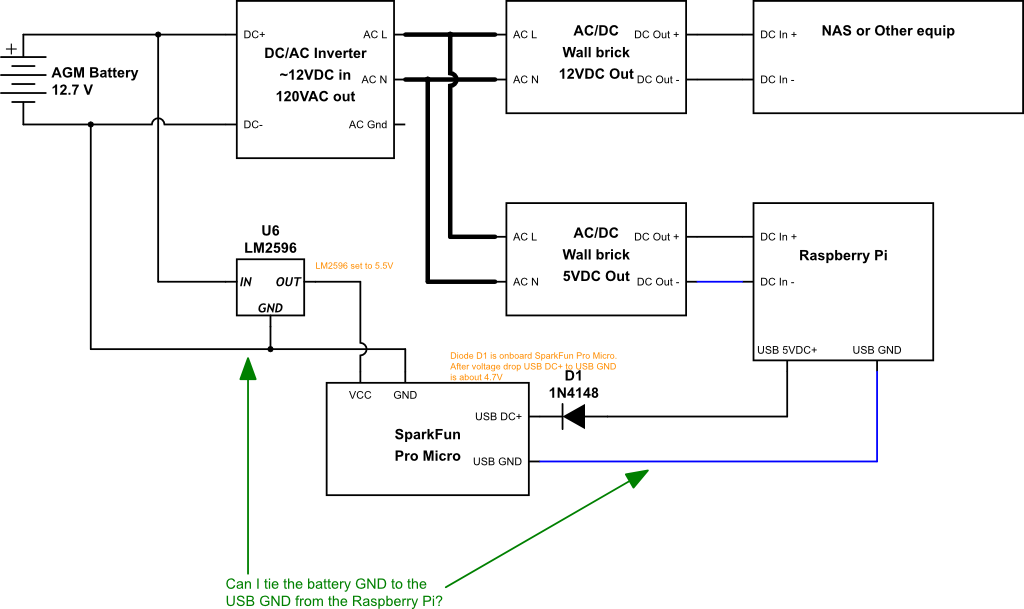
Apologies for the "sort of schematic" made up of symbols and larger components:
I'm new to drawing schematics. What I really wanted to draw was a set of connections between assemblies, not basic circuit components.
I have a working DIY UPS. On the output side, I'm powering a bunch of devices from a 12V battery bank -> inverter -> AC/DC wall bricks or possibly internal DC PSUs.
I'm also using a SparkFun Pro Micro powered directly from the battery bank so that I can use it to sense the DC voltage of the battery (I didn't show the voltage divider in the "schematic", but it's there.) In order to get accurate voltage readings, I need the Pro Micro's GND to be the same as the AGM battery, but the point of the Pro Micro is it uses a USB connection to report data back to some of the devices that are being powered by the inverter. So, those grounds are not the same.
Can I tie these grounds together? Should I? Measuring with a DMM, I've seen no more than 0.5V difference between those two GNDs.
Note that the AC GND from the inverter isn't connected to anything in my example because the wall bricks are a two prong style, but some of the things in "NAS or Other equip" does use a three prong plug to an internal PSU.

