0
\$\begingroup\$

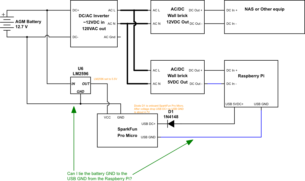
Apologies for the "sort of schematic" made up of symbols and larger components:

Example Circuit

I'm new to drawing schematics. What I really wanted to draw was a set of connections between assemblies, not basic circuit components.

I have a working DIY UPS. On the output side, I'm powering a bunch of devices from a 12V battery bank -> inverter -> AC/DC wall bricks or possibly internal DC PSUs.

I'm also using a SparkFun Pro Micro powered directly from the battery bank so that I can use it to sense the DC voltage of the battery (I didn't show the voltage divider in the "schematic", but it's there.) In order to get accurate voltage readings, I need the Pro Micro's GND to be the same as the AGM battery, but the point of the Pro Micro is it uses a USB connection to report data back to some of the devices that are being powered by the inverter. So, those grounds are not the same.

Can I tie these grounds together? Should I? Measuring with a DMM, I've seen no more than 0.5V difference between those two GNDs.

Note that the AC GND from the inverter isn't connected to anything in my example because the wall bricks are a two prong style, but some of the things in "NAS or Other equip" does use a three prong plug to an internal PSU.

\$\endgroup\$
3
  • \$\begingroup\$ why are you generating 120 Vac? ... it would make more sense to use DC-DC converters \$\endgroup\$
    – jsotola
    Commented Dec 23, 2023 at 22:11
  • \$\begingroup\$ The schematic above shows part of a DIY UPS for a home network rack. I built it as replacement for a consumer UPS, which had AC output. I agree it would be more efficient overall to use DC for all the equipment in the rack, but replacing each of the AC-DC PSUs for everything in the rack with the appropriate DC-DC converter was more than I wanted to take on. Also, in at least one two cases, the built-in equipment PSU is providing more than a single DC voltage to the equipment, so for those it wouldn't be a simple buck/boost converter. \$\endgroup\$
    – kbyrd
    Commented Dec 23, 2023 at 22:17
  • 2
    \$\begingroup\$ appologies? that drawing looks crystal clear to me! \$\endgroup\$ Commented Dec 24, 2023 at 7:12

3 Answers 3

2
\$\begingroup\$

The question is really not if you can or if you should.

They are the same ground already, as there are no separate grounds on Arduino Pro Micro.

It does not have separate grounds.

You don't need to do anything and they will already be connected through the Arduino.

\$\endgroup\$
3
  • \$\begingroup\$ Really? I'm pretty sure I didn't have continuity between RPi GND and Arduino GND when I had this setup, I assumed this was because of the diode (I may have the diode in the wrong place, maybe it's on the USB GND line? I have this taken apart right now so I can't measure it. \$\endgroup\$
    – kbyrd
    Commented Dec 23, 2023 at 21:58
  • \$\begingroup\$ @kbyrd You say you have Sparkfun.Pro Micro. The schematics are freely available, so I read them. Also, never have I encountered any Arduino or Raspberry Pi on any similar board with isolated USB ground from the main system/power ground. So you can also safely assume they are the same ground on any board. \$\endgroup\$
    – Justme
    Commented Dec 24, 2023 at 8:51
  • 1
    \$\begingroup\$ I finally got around to re-assembling this yesterday and testing this morning. Of course, you're right. When the USB cable is plugged into the Pi, I have continuity between Pi GND and Arduino GND. In my head, I was imagining that if the Pi VCC was higher than the USB voltage from the Pi, the GND would not be tied. Now that I say that out loud, that seems silly. Thanks for your answer! \$\endgroup\$
    – kbyrd
    Commented Dec 31, 2023 at 18:03
1
\$\begingroup\$

Using the USB ground as a return for anything else invites signal integrity problems. However, in this setup, tying the Pi "DC In -" to the SparkFun "GND" is a good idea: they are circuit common.

For safety, it is best to connect the "AC Gnd" to an earth ground, or whatever common conductor (vehicle chassis, boat hull, ...) is in the vicinity. If the inverter isn't double insulated, you should connect DC - to earth also.

\$\endgroup\$
1
\$\begingroup\$

You're worried about gound loops, the ungrounded isolated power supplies used by the Raspberry pi and the NAS will prevent ground loops by that path.

Connecting both the USB and the DC to the arduino probably connect them together, but this will not be problematic, because the raspberry pi supply breaks the loop.

Connecting the NAS to the raspbeery pi via ethernet will not be a problem because ethernet includes transformer isolation.

If you're only measuring voltage with the arduino you might be better off with something like INA231 which doesn't need a separate power supply, will give a more precise reading, and can also measure current.

\$\endgroup\$
2
  • \$\begingroup\$ Ethernet does include transformer isolation for data. But if you take two desktop PCs and put a STP cable between them, the PC metal cases will be connected together through the cable. \$\endgroup\$
    – Justme
    Commented Dec 24, 2023 at 8:43
  • 1
    \$\begingroup\$ It's not all shown here, but I'm doing a few things with the arduino: 1) Measure AC present/off. 2) Measure SLA DC battery voltage (as a rough measure of capacity, I know this isn't great) 3) The USB advertises itself as a HID Power device so PCs and other things treat it like a UPS that gives status reports over USB. I wasn't going to go thru the trouble of a shunt and current monitoring, but that INA231 part is interesting! I might switch out to that in rev2, thanks! \$\endgroup\$
    – kbyrd
    Commented Dec 24, 2023 at 17:41

Your Answer

By clicking “Post Your Answer”, you agree to our terms of service and acknowledge you have read our privacy policy.

Not the answer you're looking for? Browse other questions tagged or ask your own question.