1
\$\begingroup\$

enter image description here

Problem:

PCF8574 is not switching Q1 transistor correctly.

Circuit description:

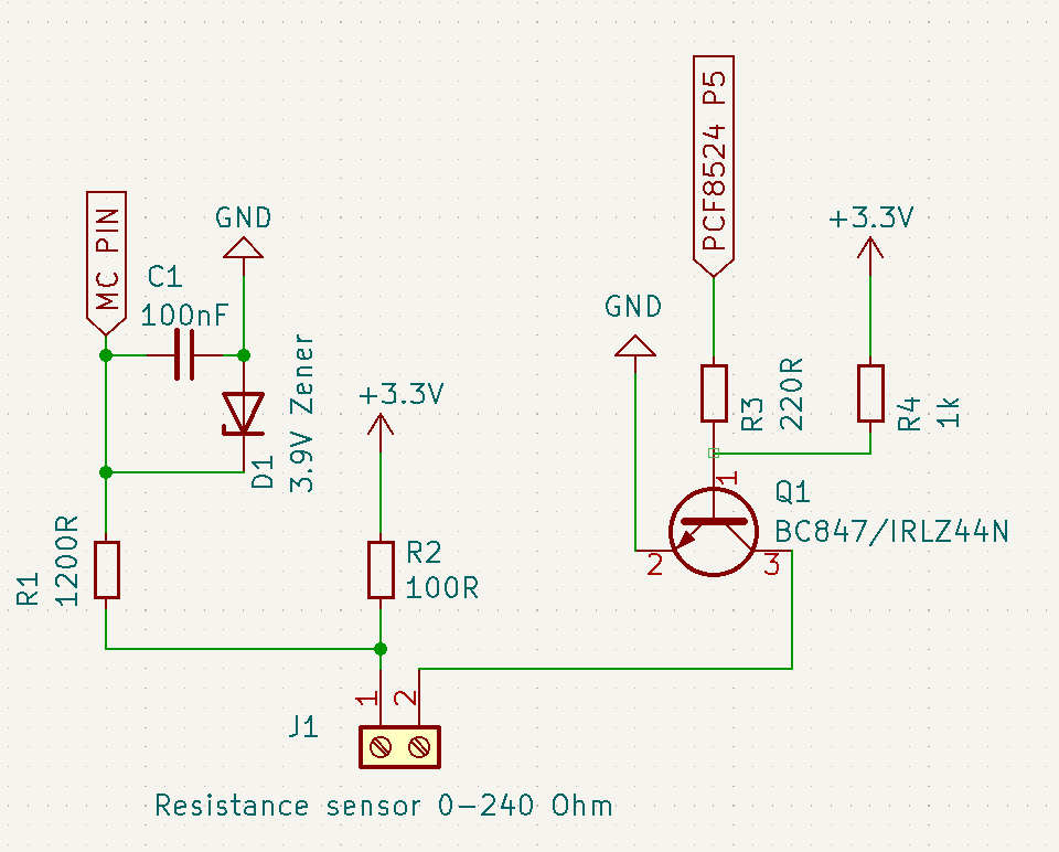
I am having issue with circuit which is being used to measure low resistance (0-240 Ohm). Resistance measurement part (left side seems to be working fine). However in order to save energy usage I would like to be able open and close this circuit on GND side using NPN transistor/N channel MOSFET driven by PCF8574 pin expander.

Unfortunately PCF8574 is not able to switch Q1 transistor correctly. It get stuck either in close or open state.

I read that PCF8574 cannot provide too much current however in low state it can sink current up to 20mA.

So I decided to use Pull-up resistor. However Q1 transistior is not switching at all. I tried BC847 NPN transistor and IRLZ44N logic level MOSFET with different R4 values 470R/1k etc.

Unfortunatelly due to other reasons high side switching is not an option.

Circuit elements:

Left side - resistance measurment side - (Voltage divider circuit with 3.3V power source)

  • C1 - Noise reduction capacitor
  • D1, R1 - Microcontroller pin overvoltage protection
  • R2 - Current supply limiter
  • J1 - Socket to comnect resistance sensor (resistance will change between 0-240 Ohm)

Right side - responsible for sink switching (NPN transistor driven by PCF8524 should open and close circuit)

  • Q1 - Low side NPN transistor or N-channel MOSFET. Used to open and close measurement circuit in order to limit energy usage
  • R3 - PCF8574 pin current limiting resistor (should limit current to 15mA)
  • R4 - VCC Pullup resistor

I will be really grateful for any help.

\$\endgroup\$
4
  • \$\begingroup\$ PCF8524 is an I2C EEPROM. Not an IO Expander. Also even if you mean PCF8574, I can't understand what the problem is. My guess is, you are not able to turn off the transistor by pulling the pin low, right? \$\endgroup\$
    – Justme
    Commented Dec 29, 2023 at 20:32
  • 1
    \$\begingroup\$ With the 1K and 220 you're (ideally) pulling the base voltage to 0.6V. If the output isn't fully grounded, or one or both of the resistors are out of tolerance, or your NPN is slightly more sensitive than average, you could be in a position of not being able to shut the transistor off at all. If you change the 1K to a 2K that should fix it. \$\endgroup\$ Commented Dec 29, 2023 at 20:56
  • \$\begingroup\$ @Justme My mistake I mean PCF8574. Exactly I am not able to switch the transistor by changing PCF8574 pin state. \$\endgroup\$
    – michalo
    Commented Dec 29, 2023 at 21:10
  • \$\begingroup\$ When I use IRLZ44N with 1k R4 pullup I see that gate voltage switch between 0V and 1.1V. It look like MOSFET is partially open in both cases and there is always some leak current. For both (0V and 1.1V gate voltages) my circuit always show measured resistance. However measured value is about 20% bigger than value measured without MOSFET (with Q1 pins 2 and 3 connected by wire). \$\endgroup\$
    – michalo
    Commented Dec 29, 2023 at 22:01

1 Answer 1

0
\$\begingroup\$

You have made the circuit so that it is impossible to turn off the BJT.

When expander output is high, there is basically 1k pull-up resistor to 3.3V (and some small weak pull up from expander to 3.3V, but that's irrelevant for now). Connecting that to BJT transistor turns it on.

But when expander output is low, assuming it goes down to 0V, it forms a resistor divider with 220 ohms pulling to 0V and 1k pulling high to 3.3V. It means the divider output is 0.595V. Connecting that to transistor base is enough to turn transistor on, at least weakly.

Basically you need to either alter the resistance values, or even better, change the circuit so that the 1k pull-up is on the expander side, not on the BJT side of the 220 ohm resistor.

\$\endgroup\$

Your Answer

By clicking “Post Your Answer”, you agree to our terms of service and acknowledge you have read our privacy policy.

Not the answer you're looking for? Browse other questions tagged or ask your own question.