4
\$\begingroup\$

I want to build an analog front-end with a 16 channel multiplexer. On each multiplexer input, there will be a voltage divider made from resistors. On the multiplexer output, there will be an op amp buffer and later on an ADC. The signals are low frequency <100Hz.
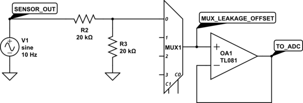
schematic

simulate this circuit – Schematic created using CircuitLab

Now what I'm concerned about is the offset introduced by the multiplexer due to leakage current. So for selecting the right part, I will need to make some calculations about the worst-case offset. I already have the correct formulas by hand. However, what confuses me is the specifications in the datasheet:

Here's an example of the MUX506IPWR multiplexer from Texas Instruments: enter image description here

The datasheet specifies three different leakage currents. I am interested in the leakage that occurs for a particular channel during measurement (when the switch is on). So initially, I though that I just have to consider the Output on-leakage \$I_{D(ON)}\$. Then I noticed that they use the term "switch".

Since a 16 channel multiplexer contains 16 switches (only one can be active at a time, and all switch outputs are connected) do I also need to consider the Output off-leakage \$I_{D(OFF)}\$ in my calculations? e.g.: $$total\ leakage\ current = 15 \cdot I_{D(OFF)} + I_{D(ON)}$$ or is this somehow already contained in the specifications of \$I_{D(ON)}\$?

\$\endgroup\$
2
  • 1
    \$\begingroup\$ General rule is that in case of apparent ambiguity in the datasheet, you should interpret it in the most unfavorable way and you'll almost always be right. \$\endgroup\$ Commented Jan 1 at 15:44
  • \$\begingroup\$ While not directly related to your question, you should have a resistor to ground on the + input of your op amp OA1. This is so you know (approximately) what the voltage on that node will be when the analog mux is disabled, by knowing the output OFF leakage current of the mux and the input bias & offset currents of your op amp. \$\endgroup\$
    – SteveSh
    Commented Jan 1 at 17:27

1 Answer 1

5
\$\begingroup\$

The bad news is that this leakage is per switch, so you do have to add all of the component currents.

The good news is that those leakage currents, at low ambient temperatures at least, are dominated by what their production test gear can measure quickly, rather than realistic leakage currents.

In practice, at 25°C, you can assume the leakage currents are typically several orders of magnitude below those worst case figures.

The difference between that 25°C typical, and over temperature worst case, is whether you are making a one-off hobby device to work in a home ambient, or 1000's off professional equipment to work over a full environmental temperature range.

\$\endgroup\$

Your Answer

By clicking “Post Your Answer”, you agree to our terms of service and acknowledge you have read our privacy policy.

Not the answer you're looking for? Browse other questions tagged or ask your own question.