0
\$\begingroup\$

I have a two-way thumb gas control which outputs two Hall-effect signals, each between 0.7 V and 4.0 V. I want to connect it to one ADC pin to control a motor.

Normally I run it with one Hall-effect signal and an extra switch that grounds an Rx pin that controls driving the motor in reverse.

Now my idea is to do it with a two-way thumb gas control connected in parallel to the ADC pin and separated with a diode.

For reversing the motor direction, I thought about using a transistor to pull the Rx pin to ground when the backward thumb gas control is active above 0.7 V.

Are there any objections regarding this?

If no, would be glad to got some tips which diode and transistor I could use and how to dimension the resistors.

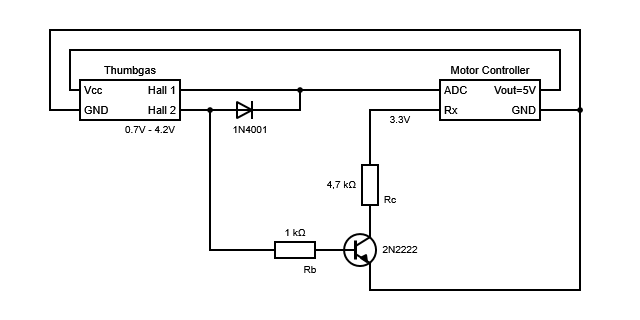
enter image description here

\$\endgroup\$
4
  • \$\begingroup\$ What is a "thumb-gas?" Is this some kind of electronic throttle for an electric bike or something? \$\endgroup\$
    – JRE
    Commented Mar 5 at 14:38
  • \$\begingroup\$ Yes, its an throttle with two ways to drive forward and backward. Thus it have two seperate hall-signals \$\endgroup\$
    – Rudi
    Commented Mar 5 at 14:47
  • 1
    \$\begingroup\$ To help get an answer can you edit the question to include links to the datasheets for the two-way thumb gas control and motor controller. \$\endgroup\$ Commented Mar 5 at 23:22
  • \$\begingroup\$ A very warm welcome to the site :-) Further to @ChesterGillon good request, can you edit your question to include new info, please don't post new info in comments. Otherwise, readers have to piece together the full question from scattered fragments. Thanks. \$\endgroup\$
    – TonyM
    Commented Mar 6 at 0:18

2 Answers 2

0
\$\begingroup\$

You cannot simply connect two hall sensor outputs, or expect, that the higher voltage overrides the lower. The analog outputs of the sensors can also sink current and would "fight" and overload each other.

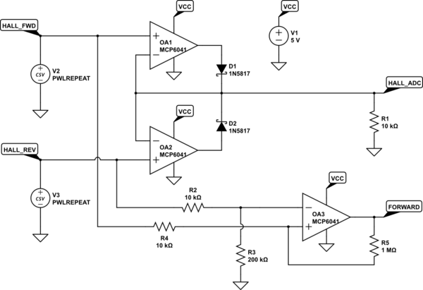
This circuit presents the higher of two input voltages HALL_FWD and HALL_REV at the output HALL_ADC. Rail to rail output OpAmps are required, because there is only a small headroom between the maximum of 4 V from the sensors and VCC.

The direction signal FORWARD is generated by comparison between HALL_FWD and HALL_REV, but a voltage divider R2/R3 reduces the HALL_REV voltage by a small amount to force a clear decision. R4 and R5 add a hysteresis to produce a stable state during noise from the hall sensor wiring.

V2 and V3 are configured to produce triangular voltages for the time domain simulator run, a forward throttle signal followed by a reverse signal.

schematic

simulate this circuit – Schematic created using CircuitLab

\$\endgroup\$
0
\$\begingroup\$

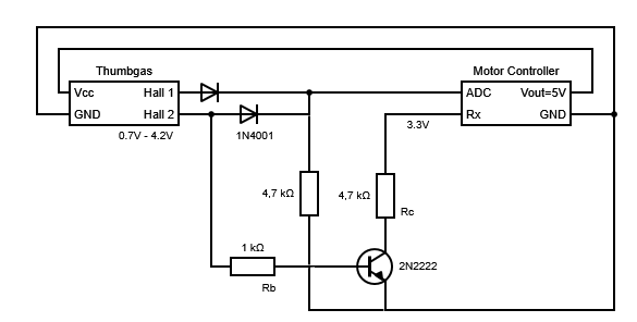
That seems like a good start but the single diode is not enough.

enter image description here

Here I've added a second diode so that neither hall can pull the output voltage down, and then added a resistor to do that pull down.

The diodes will take some of the voltage but probably only means you'll need to move your thumb a bit further for the same result.

\$\endgroup\$

Your Answer

By clicking “Post Your Answer”, you agree to our terms of service and acknowledge you have read our privacy policy.

Not the answer you're looking for? Browse other questions tagged or ask your own question.