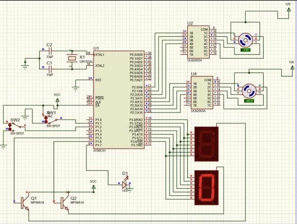
 I’m trying to implement an automated parking lot using an 8051. I’m using stepper motors to function as gates at the entrance and the exit of the parking lot that open whenever the IR sensors placed at the entrance/exit detects a vehicle passing by. I’m also keeping a count of the available slots in the lot using the sensors and I’m displaying it using two multiplexed seven segment displays. The code functions flawlessly within simulation tools like proteus but doesn’t work at all upon physical assembly.
I have physically assembled the 7 segment part of the program (the sub routine called disp) which worked properly. I don’t understand why it stops functioning once I integrate the codes for the stepper motors and the IR Sensors.
Here’s the code:
org 0000h
mov r6,#02h
mov r1,#0fh
mov r2,#0f0h
mov dptr,#table


;from maincode:
mov p2,#11H
clr p1.7
setb c
l1:jnb p1.1,ent
l2:jnb p1.2,exit
mov a,r6
acall disp
jnc l2
sjmp l1

ent:mov a,r6
dec a
mov r6,a
mov p2,#12H
l3:acall disp
jnb p1.1,l3
mov p2,#11H
mov a,r6
jz m5
sjmp l1
m5:clr c
setb p1.7
sjmp l2
exit:
clr p1.7
setb c
mov a,r6
inc a
mov r6,a
mov p2,#21H
l4:acall disp
jnb p1.2,l4
mov p2,#11H
sjmp l1


disp:mov a,r6
anl a,r1
movc a,@a+dptr
mov p3,a
setb p1.5
mov r5,#05h
mov th0,#00h
mov tl0,#00h
dj1:acall delay1
djnz r5,dj1
clr p1.5
mov th0,#00h
mov tl0,#00h
mov r5,#05h
dj4:acall delay1
djnz r5,dj4

mov a,r6
anl a,r2
swap a
movc a,@a+dptr
mov p3,a
setb p1.6
mov r5,#05h
mov th0,#00h
mov tl0,#00h
dj2:acall delay1
djnz r5,dj2
clr p1.6
mov th0,#00h
mov tl0,#00h
mov r5,#05h
dj3:acall delay1
djnz r5,dj3
ret


delay1:mov r7,#14h
m8:SETB TR0
AGAIN:JNB TF0,AGAIN
CLR TR0
CLR TF0
djnz r7,m8
RET

table:db 0c0h,0f9h,0a4h
end
And here’s 7 segment display part of the program that i tested separately:
org 0000h

mov r6,#02h
mov r1,#0fh
mov r2,#0f0h
mov dptr,#table

disp:mov a,r6
anl a,r1
movc a,@a+dptr
mov p3,a
setb p1.5
mov r5,#05h
mov th0,#00h
mov tl0,#00h
dj1:acall delay1
djnz r5,dj1
clr p1.5
mov th0,#00h
mov tl0,#00h
acall delay1

mov a,r6
anl a,r2
swap a
movc a,@a+dptr
mov p3,a
setb p1.6
mov r5,#05h
mov th0,#00h
mov tl0,#00h
dj2:acall delay1
djnz r5,dj2
clr p1.6
mov th0,#00h
mov tl0,#00h
acall delay1
sjmp disp

delay1:MOV R1,#00AH
R:SETB TR0
AGAIN:JNB TF0,AGAIN
CLR TR0
CLR TF0
DJNZ R1,R
RET

table:db 0c0h,0f9h,0a4h
end
