2
\$\begingroup\$

I'm using a PT1000 and MAX31865 to measure the temperature inside a machine.

Electronics (MAX31865 and MCU) are inside an isolated box. The PT1000 is outside and connected in two wire configuration (cable lenght approximately 30cm.) The whole system heats up to about 135°C and we also have 30PSI of pressure. The box should be sealed and thermally isolated so we don't expect the temperature to rise over 100°C inside, but there is currently no way we can check this.

When taking the measurements, it works fine up to about 130°C. After that, the temperature just keeps rising. It shows measurements of about 280°C, about double what it should be. The total measurement is about 40 minutes, and the sensor acts up for 5-10 minutes of that.

When we turn down the heat, it starts working perfectly again.

What could be the reason for this inaccuracy? Is this a known issue of the MAX3286, or is there an issue with the PT1000? I don't think that the issue is with the SPI communication or the MCU, as this would show up as corrupted data.

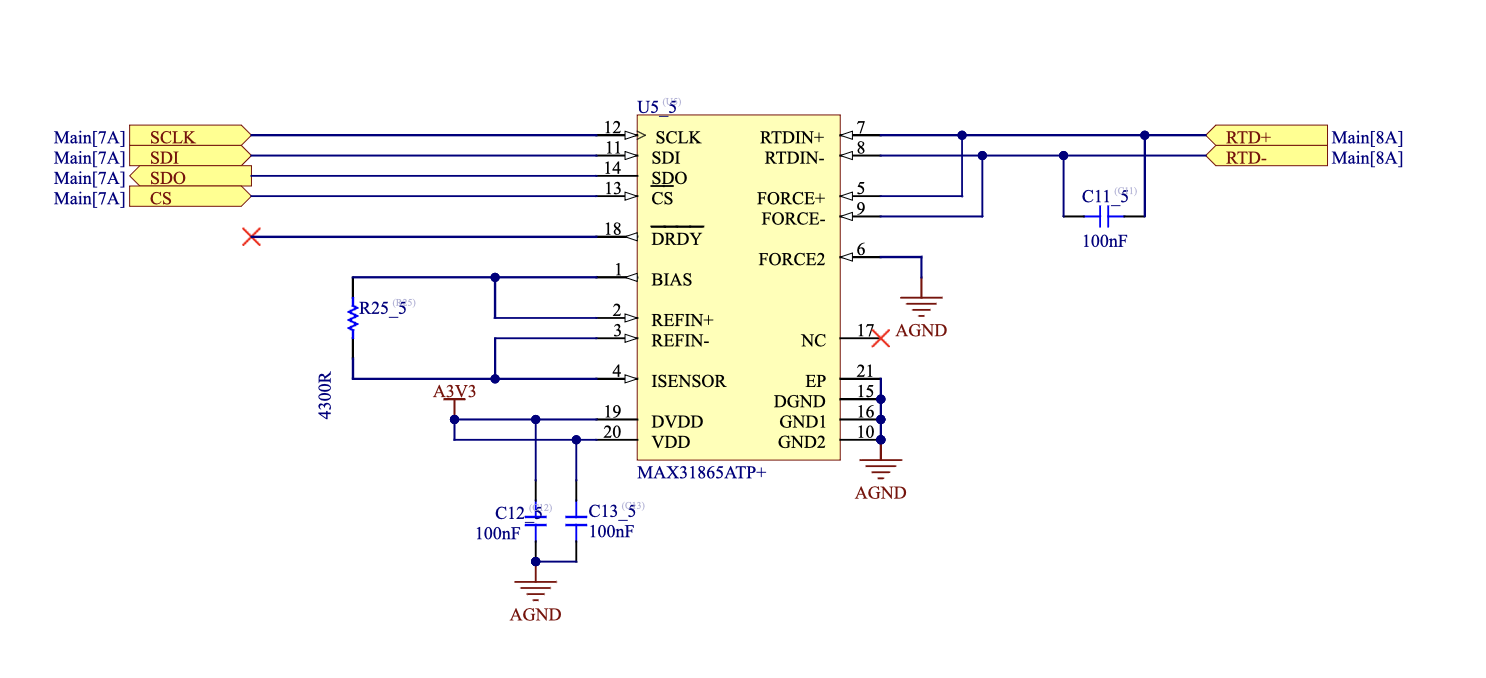
Schematic:

Schematic

Data:

Data

\$\endgroup\$
4
  • \$\begingroup\$ Is there any possibility of electrical interference that correlates with the high temperature values? \$\endgroup\$ Commented Apr 30 at 20:37
  • \$\begingroup\$ Nothing out of the ordinary I guess. The machine is certified to modern EMI standards. \$\endgroup\$
    – Felix Kunz
    Commented Apr 30 at 20:42
  • 6
    \$\begingroup\$ The setup description is unclear. What is "the whole system"? Why do you expect the inside of a sealed box with electronics in "the whole system" to have a temperature less than the outside temperature? \$\endgroup\$
    – pipe
    Commented Apr 30 at 20:47
  • \$\begingroup\$ Two-wire is not a very reliable connection. Once I met even ~300 C drift due to heating interconnectors in two-wire circuit on 80 C. \$\endgroup\$
    – Theoristos
    Commented May 7 at 4:02

4 Answers 4

4
\$\begingroup\$

The whole system heats up to about 135°C ...

... and ...

enter image description here

Figure 1. From datasheet.

\$\endgroup\$
7
  • \$\begingroup\$ The outside (where the PT1000 is) heats up to 135°C. Inside shouldn't. We did some measurements in the past and measured maximal 85-90°C in the box. This was without electronics tough. \$\endgroup\$
    – Felix Kunz
    Commented Apr 30 at 20:41
  • \$\begingroup\$ It's not clear in your question. Edit required. \$\endgroup\$
    – Transistor
    Commented Apr 30 at 20:42
  • 5
    \$\begingroup\$ If the sealed box is in a chamber that heats up to 135C, how does the inside of the box not go above 90C? \$\endgroup\$
    – Barry
    Commented Apr 30 at 22:29
  • 3
    \$\begingroup\$ @Barry By having thermal mass, isolation and limited time of operation. But I agree it should be verified. \$\endgroup\$
    – jpa
    Commented May 1 at 9:05
  • \$\begingroup\$ I'd want some independent verification of the temperature the inside reaches. A mechanical thermometer with a maximum temperature indicator is a fairly boring solution. One idea that appeals to me is putting a tidy piece of Fields metal or even candle wax in there. They'll melt around 60°C. Rose's metal gets you 100°C. This would be in addition to logging the internal temperature electronically. \$\endgroup\$
    – Chris H
    Commented May 1 at 12:16
4
\$\begingroup\$

You need some numbers. Either instrument the temperature inside the box or find a way to self-monitor. That will confirm or refute your expectations of system temperature.

Run wires out from the sensor and check it over the relevant range with a simple multimeter. Since high temperature readings result from high resistance a bad solder joint or a damaged (and thus intermittent thermally) sensor could cause this issue. If you can't do that, check every one of the connections in this simple circuit carefully visually (preferably under a decent microscope) and swap out the sensor. PCB faults are possible too, but much less likely.

If the sensor is okay, the circuit is okay, and the temperatures are okay, then it could be weirdness to do with shielding or something of that ilk. Your situation sounds a bit odd. Maybe there is something you have not mentioned that could be affecting the readings drastically.

Note that the recommended schematic calls for a 10nF capacitor across the sensor and you have used 100nF. If the MAX32865 is not well designed it's possible to imagine that causing instability, but that would be a long shot. It can also affect the reading unless the longer time constant is accounted for.

\$\endgroup\$
1
  • \$\begingroup\$ The first thing I'd do is just repeat the experiment with the PT1000 right next to the board, inside the enclosure. \$\endgroup\$
    – Chris H
    Commented May 1 at 12:20
0
\$\begingroup\$

There are some good electronics and experimental answers and comments. Here (unusually for me) I propose a theoretical check, as well as another failure mode.

Make a 1-D thermal model

You don't need thermal simulation software for a crude model, just use Fourier's law. That only needs the ΔT across the box wall, the surface area of the box, and the thermal conductivity of the box, to work out how much heat flow you'll get. You also need to know the total heat capacity of the contents of the box, worked out from the specific heat capacity of each material inside and its mass. Most materials in electronic devices won't contribute much, so concentrate on the metals (any batteries will contribute quite a bit too).

You can start by taking a worst case value for ΔT: 130°C on the outside and your starting temperature on the inside. Assuming perfect coverage of your insulating material is a bit of a best-case estimate; hopefully your wires are thin. You will, I hope, have specs for your insulating material.

Then with the heat flow and the heat capacity you can easily work out the rate of temperature rise under these crude assumptions, and see if the internal temperature will get too hot within anything like the timescales you observe. A numerical model that changes ΔT as the inside heats up is still pretty trivial; that will make things look better as the reducing ΔT will drive less heat flow.

Check any batteries

Further, if it is battery powered, you should check what the batteries do at the temperatures in question. Their output voltages and internal resistances will change with temperature. If the voltage ends up outside the rated range for your ICs you'll have undefined behaviour.

And of course measure the internal T, as we said before

\$\endgroup\$
0
\$\begingroup\$

Verify the temperature stability of your Rsense (4.3k per schematic) resistor.

That plays a pretty important role in setting up the measurement of the RTD element per the MAX31865 datasheet. You indicate in comments that the temp in your enclosure gets up into the 90C range, the Rsense resistor could even be hotter than the ambient of the enclosure...

\$\endgroup\$

Your Answer

By clicking “Post Your Answer”, you agree to our terms of service and acknowledge you have read our privacy policy.

Not the answer you're looking for? Browse other questions tagged or ask your own question.