2
\$\begingroup\$

I am a beginner concerning electronics and would love to learn something new. I have a Teensy 4.1 and would like to calculate an encoder's speed. The encoder is built in into a system which supplies it with 12V. So the output I can get is a square wave with too high of a voltage level.
Since the µC cannot cope with such high voltages I need to use a voltage divider.
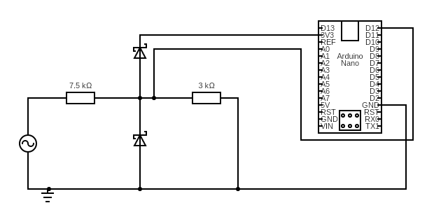
To get the correct ratio I have chosen R_1=7.5kOhm and R_2=3kOhm. I have also added Schottky Diodes to clamp the voltage between -0.2V and +3.5V.

When I connect everything according to the following schematic and measure between µC input pin and GND I get the following measurment on the scope, not exactly what I expected. Note that the different motor speed, so higher pulse frequency is not the point, the shape of the signal is unexpected.
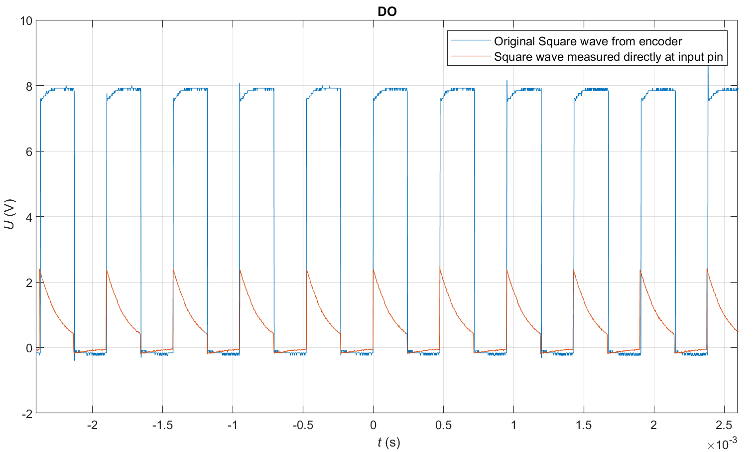
Input and output of the system together Schematic (note that I used an Arduino Nano in the drawing, the program did not have a Teensy to wire things upSchematic of the circuit:
Do you have an idea of what could have gone wrong here? Of course I have done a compensation of my scope before measuring. With the voltage divider applied I get negative spikes which I can compensate all the way down to -200mV. This is within range of the DIO ports so should be fine. The rising edge can be detected by the µC, so all is fine but I would just like to understand where the capacitance comes from.Is this a common effect? Can I somehow compensate this so that I get more of a rectangle? Do I need to connect it up differently?
I could be happy with the results I have since I still have a nice rising edge to trigger an interrupt on the µC, however I would still like to understand what is happening here. I would have just expected a square wave with a lower HIGH-level.

Would be happy to learn what is happening here!

EDIT: I have attached a nicer looking schematic and both measurements in one graph. I have now changed to a Teensy 4.1 since that will be the more long term solution for this application. Many people mentioned a capacitive coupling, would this likely be from the driving circuit? As stated, it is a black box, so I do not have any information on the driving circuit. I need to use the 12V encoder, I could also probably drive it from a µC pin with some sort of circuitry making it possible to supply 12V, but I thought since I already have a working system I could just tap into it and use the signal.

To rule out measurement errors I have soldered a nice ground lead to the GND pin to hook my scope onto. I must confess the initial measurements were with a crocodile clip attached to the resistor lead, thought that would be good enough. Got the same results, so I would say it was good enough haha!

I have seen threads like this, could this be my problem and I could compensate it with caps in parallel to the resistors in my voltage divider? I always thought I needed an inductor to counter the effects of a capacitor, what am I thinking wrong here?

Thanks for your help already!

\$\endgroup\$
12
  • \$\begingroup\$ What is happening is that you assume the output being ideal 12V/0V square wave output, but in fact the output circuitry really is unknown and it causes this waveform when loaded with your resistive divider. Do you have any schematics or manual about the system, are you free to put arbitrary load to the signal? Do you know how much you can load the signal? Have you got the grounds of the two systems and the scope connected? \$\endgroup\$
    – Justme
    Commented May 28 at 7:34
  • \$\begingroup\$ First off, it is very unlikely that the inputs can absorb 20 mA. They may be able to deliver that much. That's common. But that is when configured as an output, not when configured as an input. So I believe you are misinterpreting something there. And also, we need to know what's driving all this and I'd like to see both traces at once, too. \$\endgroup\$ Commented May 28 at 7:36
  • 1
    \$\begingroup\$ For me that looks a lot like a series capacitive effect (high pass), which could point at a bad connection. Check with a multimeter that all your connections are solid. \$\endgroup\$
    – Arsenal
    Commented May 28 at 7:53
  • \$\begingroup\$ @Justme that is a good point! sadly the system is a black box and that is why I would like to use a microcontroller to analyze the signal. I do not have access to any schematics or manuals. Would it help to increase my resistive values in order to have a smaller load on the system? I have connected ground of the driving system as well as scope and voltage divider to the same point. \$\endgroup\$ Commented May 28 at 7:54
  • \$\begingroup\$ @periblepsis That makes sense, however I based it on forum.arduino.cc/t/maximum-current-from-a-data-pin/88830/2. Driving circuit is unknown, having both signals in one plot is a good idea, will go forward measuring that today! \$\endgroup\$ Commented May 28 at 7:57

1 Answer 1

3
\$\begingroup\$

You can't just design voltage dividers/signal conditioners without understanding the charactoristics of the source signal first - that's called putting the cart in front of the horse.

Here's what you need to do. Forget the voltage divider and microcontroller for now. Measure: the open-circuit signal of the encoder, encoder with 47k resistor, encoder with 10k resistor, encoder with 5k1 resistor, encoder with 1k resistor. The exact resistors don't even matter; the point is you want to see how the signal gets attenuated as loading is increased. Test these cases over wide operating frequencies.

There will be a resistance in which the encoder output falls to 1/2 its amplitude. In first order, this will be the source impedance. Ideally, the signal will still be square and sharp. If you are still getting decays in the output, things get more complicated. You may need a pullup resistor (encoder might be open-collector. They usually are.). If that's the case, try various pullups and re-characterize the signal. 10k is a good place to start. Don't go too low (<470 ohm) or you risk blowing out the output transistor (if there is one).

The treatment of the downstream signal conditioning is predicated on the encoder output: If it's push-pull with high output impedance (first case) you need to soften your voltage divider with higher value resistors. If you have an open-collector output, you just have to clamp the output to the 3.3V rail (again, 10k pullup is reasonable for current limiting and low enough for sharp edges - lower values will sharpen the rise time at the expense of more current flow. Lower values will save current consumption at the the expense of softer rise time edges. There's not a hard value here and you will see that the resistor value has only a small effect over the regime we are talking about here).

Adding inductors or capacitors anywhere won't help you in either case for your problem.

\$\endgroup\$
1
  • 1
    \$\begingroup\$ Thank you for the detailed decription, that makes sense! I do have a datasheet available for the encoder, it is indeed a push-pull encoder, so no open collector. Your explaination makes sense though, especially finding the source impedance is a smart method! So for my application this means that I will probably have to soften the voltage divider (aka. increase resistances, this reduces the load on the source). Thanks heaps @MOSFET! \$\endgroup\$ Commented May 31 at 6:53

Your Answer

By clicking “Post Your Answer”, you agree to our terms of service and acknowledge you have read our privacy policy.

Not the answer you're looking for? Browse other questions tagged or ask your own question.