1
\$\begingroup\$

I'm trying to breadboard a simple circuit testing a TI UC3708N gate driver, which I need to drive from an AWG square wave. Since the AWG has limited amplitude (and perhaps limited current), I made the following simple pre-amp:

enter image description here

which should provide suitable voltage: enter image description here
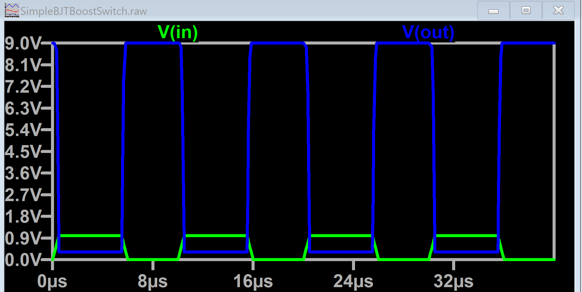
When I breadboard the pre-amp, I get results as expected. However, when I hook the pre-amp to the input of the TI UC3708N gate driver, the voltage of the output of the pre-amp changes. I'm having trouble getting steady readings (perhaps due to the fact that I'm using a handheld oscilloscope/AWG on a breadboard), but it seems to oscillate between 1.5V and 4.5V.

The output of the gate driver is consistently high, which, given those inputs, is expected. But why does hooking it up lower the output of the pre-amp?

Note: If helpful, see https://electronics.stackexchange.com/a/717410/66365


Update

Perhaps the issue is that gate driver has an internal pull-up resistor, and I need lower source impedance to drive it? If so, I should be able to solve it with an emitter follower to increase the current - is that correct?

\$\endgroup\$
6
  • \$\begingroup\$ Please place a resistor in series with the base. \$\endgroup\$
    – winny
    Commented Jun 25 at 16:51
  • \$\begingroup\$ Have you tried just driving it with your AWG? They are usually much more capable than the driver circuit you drew. \$\endgroup\$
    – John Doty
    Commented Jun 25 at 16:52
  • \$\begingroup\$ @JohnDoty Yes, I couldn't get it to drive from the AWG. Perhaps you have a suggestion: please see electronics.stackexchange.com/questions/717401/… \$\endgroup\$ Commented Jun 25 at 19:25
  • \$\begingroup\$ @winny Can you please explain why I should put a resistor in series with the base and what this will accomplish? \$\endgroup\$ Commented Jun 25 at 19:26
  • \$\begingroup\$ It's supposedly CMOS compatible. An AWG usually has a 50 ohm output resistance similar to CMOS. Are you sure you're enabling it right? \$\endgroup\$
    – John Doty
    Commented Jun 25 at 19:36

1 Answer 1

3
\$\begingroup\$

You're going to need to drive both the high and low harder.

With your circuit a current of 100 uA, which is within the gate driver's specced input high range, will drop 3.9 V across the collector resistor.

Typical input low current for your gate driver is 600 uA, and it could be as much as 1 mA, so that's 0.6 V to 1 V across the emitter resistor, plus \$V_{CE}\$ which could be another half volt. This means the output voltage of your circuit is going to be right around what you're measuring, half the supply voltage when it's high, a bit more than a volt when low.

You would need lower output impedance from your amplifier, you might be able to reduce the resistor values, but better would be to use something like a common emitter for gain and push-pull emitter follower to increase the available current.

\$\endgroup\$
3
  • \$\begingroup\$ Reducing the emitter resistor solved it! \$\endgroup\$ Commented Jun 25 at 20:24
  • \$\begingroup\$ @SRobertJames Great. The high is probably okay with the lower voltage since it only needs to be over 2 V, but the low wasn't getting low enough. Just make sure you're not going to have too much base current, you could get away with no base resistor with 1k in the emitter, you might want to add one now though. With a base resistor you could probably eliminate the emitter resistor. \$\endgroup\$
    – GodJihyo
    Commented Jun 25 at 21:24
  • \$\begingroup\$ LTspice shows almost 0 current through the transistor, even with only 1 Ohm emitter resistor and no base resistor. Why is that? \$\endgroup\$ Commented Jun 25 at 22:06

Your Answer

By clicking “Post Your Answer”, you agree to our terms of service and acknowledge you have read our privacy policy.

Not the answer you're looking for? Browse other questions tagged or ask your own question.