6
\$\begingroup\$

I'm used to choosing SMD resistance package size according to the power they will need to dissipate (+ a margin). i.e: 0603: 0.1W, 0805: 0.125W, 1206: 0.25W, 1210: 0.5W, like you can find here.

But more and more, we can find components with much higher power in the same package. Example here 0805: 0.5W ! It is 4 times the power rating of a regular one.

The test conditions and tolerances looks roughly similar.
The package doesn't seem to have a better dissipative material.
So what magic do they use to quadruple the power rating?

Can I assume that I can replace an old 1210:0.5W by a new 0805:0.5W?

To choose the power rating, I usually add like 40% of margin (when I don't need precision), can I use the same rule with these new resistors?

\$\endgroup\$
3
  • \$\begingroup\$ Those wattage ratings are just minimum ones that it is guaranteed to handle. Some parts can handle more, but if you rely on that, then you'll specifiy a non-standard component which might be more expensive and harder to procure. Also, just because it can handle 0.5W it doesn't automatically mean that it has as good thermal dissipation as a 1210. You really have to read all the fine print in the datasheet, including all the thermal characteristics. \$\endgroup\$
    – Lundin
    Commented Nov 27 at 15:34
  • \$\begingroup\$ Exactly how they increase the power handling is likely a manufacturing secret, though I might guess that things like increasing the size of the element inside the package might help to dissipate heat over a wider area, and hence increase the power handling. \$\endgroup\$
    – LordTeddy
    Commented Nov 27 at 15:55
  • \$\begingroup\$ Thank you @citizen for the English corrections. \$\endgroup\$
    – AdriZ
    Commented Nov 28 at 14:26

4 Answers 4

6
\$\begingroup\$

There is a fine print in the datasheet:

enter image description here

In other words, if you put enough copper around the resistor pads to give it Rth < 110K/W to ambient, then the 0.5W power rating applies to the 0805 resistor.

Otherwise, with tiny pads and skinny traces, it will heat up as much as a standard resistor, and since the max temperature is the same (155°C), and there's no reason for heat loss through convection and radiation to be different, the power rating should be identical, ie 0.125W.

Can I assume that I can replace an old 1210:0.5W by a new 0805:0.5W?

I would say yes, as long as you put enough copper around the pads to meet the spec. So in the end, with copper included, it will probably take as much space as the 1210. However, if the resistor is connected to a power or ground plane with a few vias to wick the heat, then you can use that existing copper area to cool it without using valuable space on top layer. Likewise if it already sits on a copper pour or fat trace which you need to have anyway, which is usually the case for current sense resistors, then the traces will do double duty as heat sinks. It's no different than using the tab of a SMD LDO to dump heat into a power or ground plane. But you'd need to check the thermal resistance to ambient.

\$\endgroup\$
1
  • \$\begingroup\$ Thanks a lot. That was one of my concerns. \$\endgroup\$
    – AdriZ
    Commented Nov 28 at 10:28
12
\$\begingroup\$

There are two main methods used that can dramatically increase the power rating of a chip resistor. The easier of these is to simply use larger metal terminals to conduct more heat to the PCB and away from the resistor. This is seen somewhat frequently, such as in Susumu's HRG series:
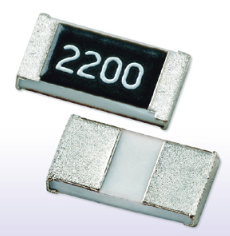
enter image description here

The downside is that, to get the improved thermal performance, you do need to use a different PCB footprint than the standard one for the resistor's size. The extent of the terminals also means these resistors have much lower creepage and clearance than conventional resistors of the same size, which may matter for high-voltage applications.


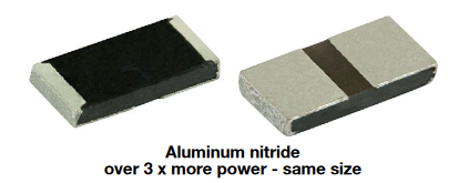
The other common method, seen in some very high-power chip resistors, is to use a substrate material with a higher thermal conductivity. Most chip resistors use cheap, easily processed alumina ceramic (Al₂O₃), but alumina's thermal conductivity leaves something to be desired at only about 30 W·m⁻¹·K⁻¹. Metals have much higher thermal conductivities, around 400 W·m⁻¹·K⁻¹ for copper. But using a metal substrate is impractical, because the substrate needs to be electrically insulating--so ceramics are used. The highest thermal conductivity of any electrically insulating material (or indeed any known material at all) is that of diamond, but that's impractical for obvious reasons, so the next best ceramics, beryllium oxide (BeO) and aluminum nitride (AlN), are used instead. Of the two, BeO has a higher thermal conductivity that can be as high as 330 W·m⁻¹·K⁻¹, but because it's extremely toxic, it's only used in the most demanding cases. AlN, with a thermal conductivity of about 200 W·m⁻¹·K⁻¹, is preferred for most applications. However, AlN and BeO are both less chemically resistant than Al₂O₃ (AlN can even be damaged very slowly by exposure to water), so care should be taken if they are to be used in harsh environments.

AlN substrates are used in many of the highest-power chip resistors out there, like Barry Industries' RP0402-2Q, which manages a 1 W power rating in 0402 size, provided sufficient active cooling.

Some resistors combine both methods, like Vishay Dale's RCP series, which has an AlN substrate and comes with either standard or extra-wide terminals, managing as high as 3.5 W in free air, or 22 W actively cooled, in 2512 size. Note the grey-to-brown color of the substrate; this is indicative of AlN.
enter image description here

A very few resistors try to eke out every last milliwatt they can, and use a beryllium oxide substrate. Barry Industries' RP2010-96, for instance, claims a 32 W rating in 2010 size, provided active cooling.


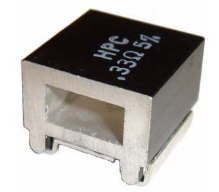
There is also the interesting, though now discontinued, HPC series from Stackpole, which managed to get quite high power ratings of 5 W free air or 12 W forced-convection by the novel approach of just integrating a small heatsink onto the component itself. What substrate is used between the element and heatsink is not mentioned; it's most likely simply Al₂O₃. The heatsink itself appears to be aluminum, going by the picture.
enter image description here


Regardless of the method used to increase the power rating, other aspects of the resistor's design need to be considered as well. Common methods of trimming a film resistor to the proper value create a resistance that's distributed unevenly across the substrate, which means that there will be part of the resistor that heat up more than others--essentially creating weak spots in the resistor. Spreading the dissipation more evenly with a more complicated structure will improve power handling capability, with a particularly strong effect on pulse load capability.

This is why composition resistors, which are made of a homogeneous mixture of conductive material and filler, have such high pulse load ratings.

\$\endgroup\$
7
  • 1
    \$\begingroup\$ With recent advances in artificial diamond manufacturing, using diamonds as heat sinks may not be so impractical, or even that expensive. :-) \$\endgroup\$
    – oakad
    Commented Nov 28 at 5:44
  • 2
    \$\begingroup\$ @oakad Somebody already has the budget for that! \$\endgroup\$
    – user71659
    Commented Nov 28 at 6:45
  • \$\begingroup\$ Thank you so much for this very detailed reply! \$\endgroup\$
    – AdriZ
    Commented Nov 28 at 10:29
  • \$\begingroup\$ It seems they don't use that two main methods in the example I've sent, isn't it? In that case, the reason should be the @bobflux reply, isn't it? \$\endgroup\$
    – AdriZ
    Commented Nov 28 at 10:34
  • 1
    \$\begingroup\$ @AdriZ Yes, your example is only slightly higher power than normal, so it could very well even be exactly the same resistor as a lower-power one, but specified under different conditions. You can always eke out a little more power by simply cooling the part better, though you can't get that much more with traditional chip resistor designs, as hot spots become a limiting factor. \$\endgroup\$
    – Hearth
    Commented Nov 28 at 16:38
3
\$\begingroup\$

So what magic do they use to quadruple the power rating?

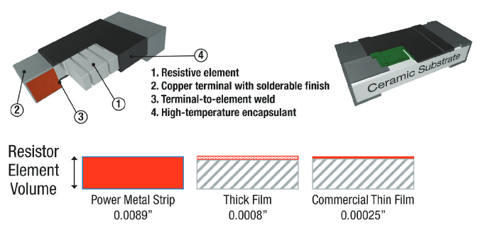
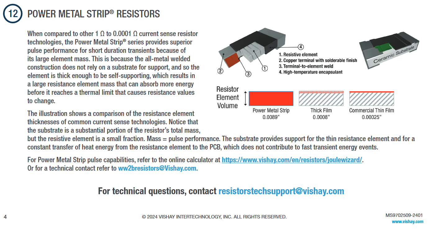
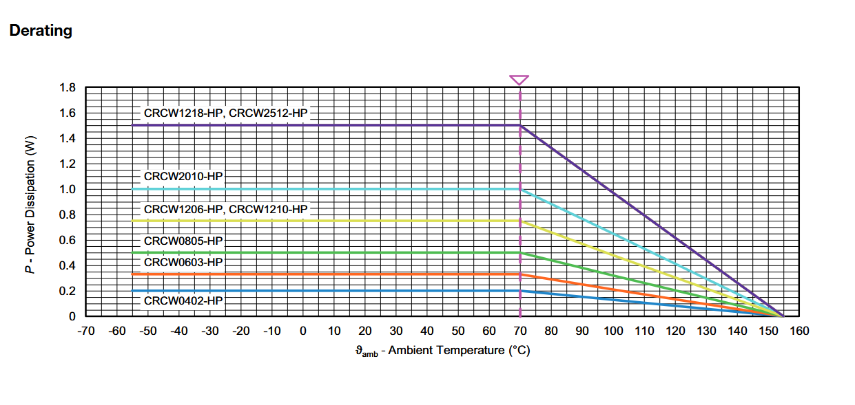
More resistive metal, no insulator base and > 4x the cost, same size, weight.

For a 5k Reel in 1 Ohm 805 5% D-K has different prices:

  • HP 1/2W 5,000 pc $0.04279 $213.95 CRCW08051R00JNEAHP

  • HP 1/8W 5,000 $0.09733 $486.65 CRCW08051R00JNEAIF

  • Std 1/8W 5,000 $0.01930 $96.50 CRCW08051R00JNTA

  • Std 1/8W 5,000 $0.00729 $36.45 CRCW08051R00JNEA

D-K $ REF

Image Source: 12 THINGS TO KNOW ABOUT RESISTORS IN PULSE LOAD APPLICATIONS
https://www.vishay.com/docs/48516/_ms9702509-2401-vishaychecklistpulseload.pdf

enter image description hereenter image description here

Source: https://www.vishay.com/docs/20043/crcwhpe3.pdf The 0 Ohm Jumper has nice specs too. 2A

\$\endgroup\$
2
\$\begingroup\$

There are several ways to increase the power rating of a resistor.

The key for increasing power rating is improving the heat transfer, as the dissipated power is mostly limited by the terminal temperature of the element and the package.

Different materials produce different mass, conductivity and thermal conductivity. New manufacturing techniques allow for a better heat transfer from the resistive element to the component pads. Also different trimming shapes can affect the power rating.

The manufacturer does not usually provide this information so it might seem like "magic", but if he guarantees certain power at certain temperature, you can usually believe it. As long as the manufacturer has some reputation, they don't want to lose it.

\$\endgroup\$

Your Answer

By clicking “Post Your Answer”, you agree to our terms of service and acknowledge you have read our privacy policy.

Not the answer you're looking for? Browse other questions tagged or ask your own question.