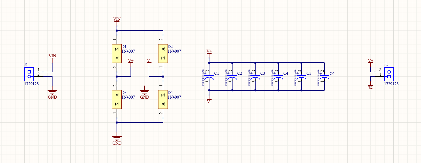
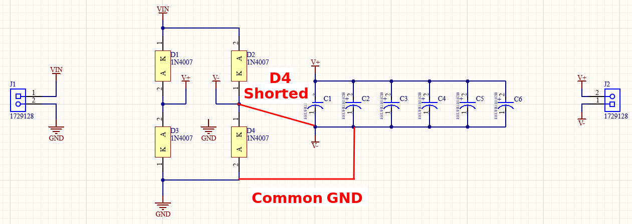
I am putting together a full bridge rectifier, see schematics. The load is connected to V+ and V-. Capacitors as low ESR and with respect to the standard formula.

simulate this circuit – Schematic created using CircuitLab
The simulation went as expected. However, when I physically realized this circuit on PCB, something strange happened. Connecting 5 V AC sinusoidal function generator provided about 4 V at output. But when I increased the amplitude (peak-to-peak voltage) of input signal, the voltage at ouput did not grow "linearly" and instead started to saturate. For example, for 10 V at input, the output voltage was only 6.5 V. I returned back to the simulation and tried it again, but nothing strange occured.
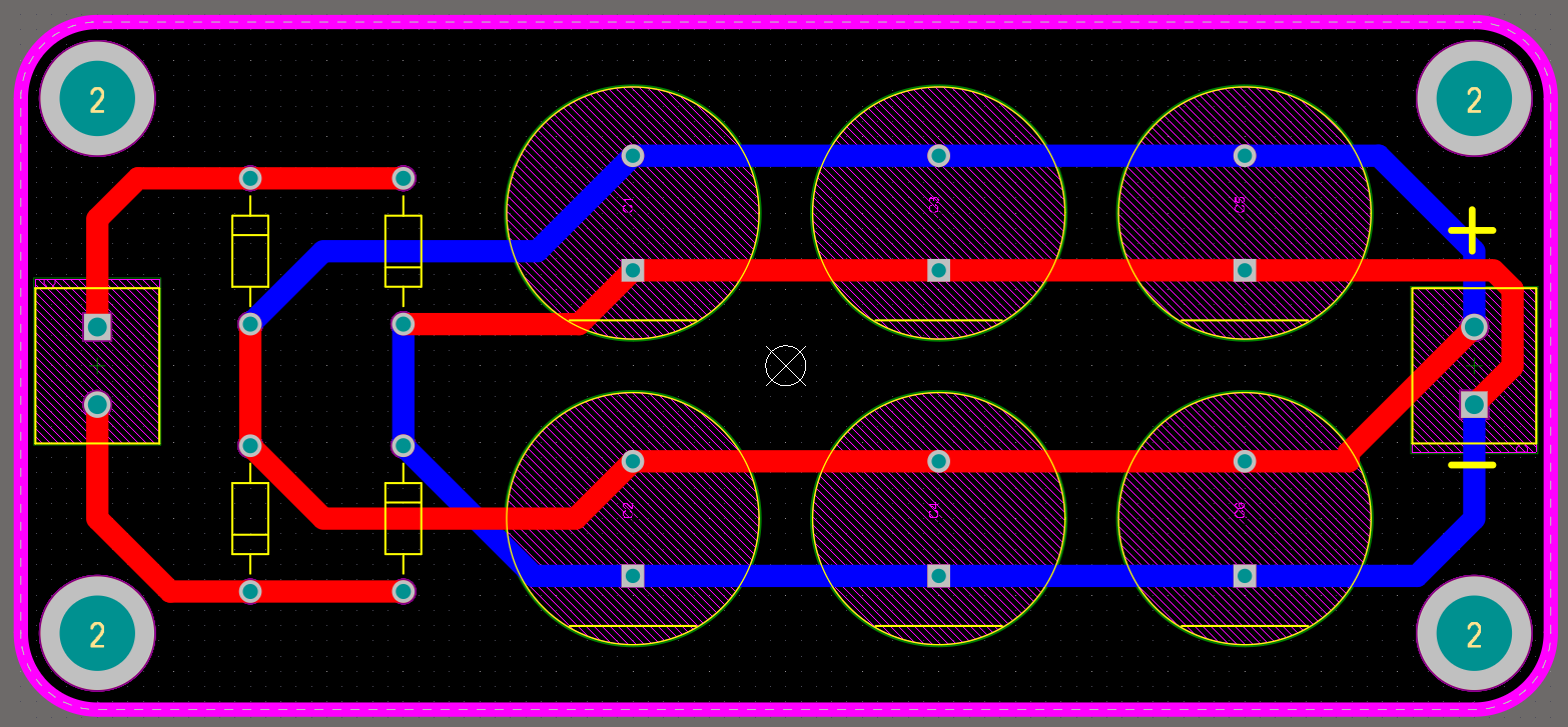
I measured the ouput voltage with oscilloscope with input impedance set to 1 MOhm. Am I missing something? I am adding the layout of my bridge rectifier.


