2
\$\begingroup\$

I have an unipolar stepper motor that im driving with an Arduino. As a driver for the motor i bought a ULN2004 driver chip from Ebay. Or so i thought. I might be missing something, but the chip i received has 9 pins on each side, not 8 as my sketch illustrates, and the number on it is ULN2804, not ULN2004.
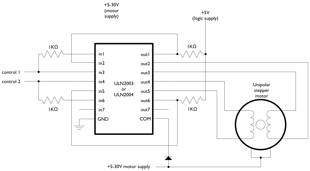
enter image description here

The link to the data sheet on the ULN2004 listing i bought from spinatronics says it's a ULN2804 chip. I'm unexperienced in how manufacturers set the numbers on the chips.

Have i bought the wrong chip, or can a ULN2804 driver be used the same way as a ULN2004?

How do i then change my sketch to implement the last two additional pins of the chip?

\$\endgroup\$
3
  • \$\begingroup\$ Please capitalize "I" when referring to yourself. (I've edited several other questions with this issue.) \$\endgroup\$
    – JYelton
    Commented Nov 18, 2013 at 1:11
  • \$\begingroup\$ @JYelton Thanks for the feedback! As I am not a native speak, those rules are easily forgotten. Will try to improve now that I'm aware of it :-) \$\endgroup\$
    – bogen
    Commented Nov 18, 2013 at 10:55
  • 1
    \$\begingroup\$ Thanks for the response. A lot of people seem to think I'm attacking them, but I'm just interested in the quality of the site. Thanks for your efforts! \$\endgroup\$
    – JYelton
    Commented Nov 18, 2013 at 16:34

1 Answer 1

2
\$\begingroup\$

Here's the pdf for the ULN2004 chip

It looks like the same application and same specs, set of darlington arrays. ULN2004 has 7 circuits as oppose to ULN2804 which has 8. Both carry 6-15V (CMOS, PMOS compatible inputs), Output currents of 500 mA per driver, and Output Voltage of 50V

It might've been a careless mistake derived from laziness since the chips have the same type of circuitries.

Because these chips are practically the same, you can utilize 2804 the same way as 2004. Only in this circuit, you'd have in8, out8 pins setup the same as in7 and out7

\$\endgroup\$
3
  • \$\begingroup\$ So, can it work to power my stepper? And how do i alter the sketch to work with an extra pin on the chip? \$\endgroup\$
    – bogen
    Commented Jul 22, 2013 at 15:15
  • \$\begingroup\$ This example looks fine. These chips are commonly use for this application. You can find many tutorials online. Here's one Arduino Darlington-array stepper-motor \$\endgroup\$
    – Iancovici
    Commented Jul 22, 2013 at 15:19
  • \$\begingroup\$ Thanks! Just not sure what i do with my driver having one more pin than the one in the toturial. I'm not experienced enough to make up my own sheet completely on my own. \$\endgroup\$
    – bogen
    Commented Jul 22, 2013 at 15:24

Your Answer

By clicking “Post Your Answer”, you agree to our terms of service and acknowledge you have read our privacy policy.

Not the answer you're looking for? Browse other questions tagged or ask your own question.