5
\$\begingroup\$

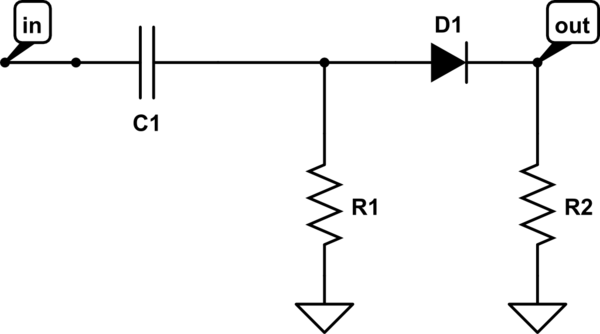
In the art of electronics book, page 49, 2nd edition, they show a signal rectifier circuit (a circuit that tosses away the negative part of a signal). Here it is:

schematic

simulate this circuit – Schematic created using CircuitLab

I think the capacitor is there to block out DC. Is that right? What are the uses of the two resistors? Couldn't the same goal be accomplished by taking them out?

I think R2 between GND and the diode is needed for the diode to work correctly, as a way for the circuit to drop the needed voltage so the voltage drop across the diode stays at the diode forward voltage drop.

What about R1?

Thank you very much.

\$\endgroup\$

2 Answers 2

9
\$\begingroup\$

Assuming ideal components, when the diode is "on", the equivalent circuit is:
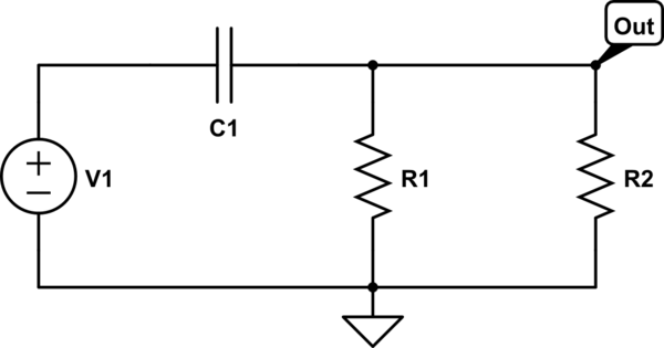
schematic

simulate this circuit – Schematic created using CircuitLab

The charging current clockwise through C1 produces a voltage across the parallel combination of resistors.

When the diode is "off", the equivalent circuit is:
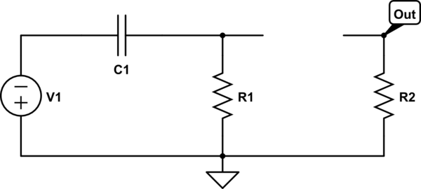
schematic

simulate this circuit

Now, you can see that R1 is provide a path for a counter-clockwise current to discharge the capacitor.

Also, see that R2 is required to pull the output voltage to zero while the diode is off.


Why is the path that R1 provides needed? if it's not there, then there is an open-circuit, no current flows. Theoretically the end result should be the same: the negative part of the signal does not appear at the output.

If there is no path for a counter-clockwise current through the capacitor, the voltage across the capacitor will only increase and this voltage will oppose the positive signal voltage. Eventually, the capacitor voltage will be large enough that the diode will not turn on and the output voltage will be zero.

Below is a simulation I ran without R1. The top trace is the voltage across the capacitor; the bottom trace is the output voltage. The input source is 1kHz sine wave.
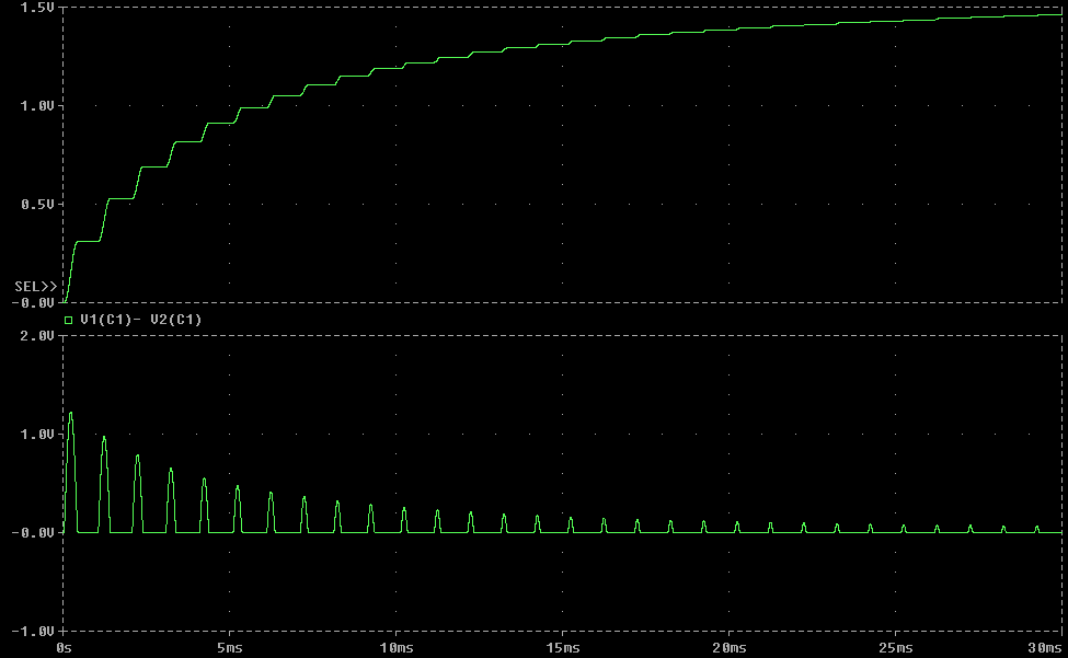
enter image description here

Note that the voltage across the capacitor increases while the diode is on but doesn't decrease while the diode is off. Note the effect of this on the output voltage.
\$\endgroup\$
2
  • \$\begingroup\$ Why is the path that R1 provides needed? if it's not there, then there is an open-circuit, no current flows. Theoretically the end result should be the same: the negative part of the signal does not appear at the output. \$\endgroup\$ Commented Sep 18, 2013 at 22:49
  • \$\begingroup\$ @DouglasEdward, if there is no path for a CCW current through the capacitor, the capacitor will eventually charge to about the peak positive signal voltage and this voltage will oppose the signal voltage such that the diode never turns on and the output is always zero. This is easy to simulate and verify. I'll update my answer. \$\endgroup\$ Commented Sep 18, 2013 at 23:15
4
\$\begingroup\$

For the capacitor to work correctly, it needs R1 as path to ground to discharge (during negative half wave). Otherwise it would just charge to peak value and from then on nothing happens as the diode no longer gets forward biased.

Look at R2 as the load of the circuit and indeed to forward bias the diode.

\$\endgroup\$

Your Answer

By clicking “Post Your Answer”, you agree to our terms of service and acknowledge you have read our privacy policy.

Not the answer you're looking for? Browse other questions tagged or ask your own question.