4
\$\begingroup\$

Early on in the book The Art of Electronics (p.15, 2nd edition) a voltage divider circuit is described: an input voltage \$V_{in}\$ over a tunnel diode \$D\$ and a resistor \$R\$, and an output voltage \$V_{out}\$ the voltage across the resistor.

It is then written that a change in \$V_{in}\$, denoted \$v_{sig}\$, results in an (amplified) change \$v_{out}\$ in the output:

\$v_{out} = \frac{R}{R + r_{t}} \cdot v_{in}\$

where \$r_{t}\$ is (negative) dynamic resistance of the diode \$D\$.

Unfortunately no derivation is given.

I have been trying for the last two hours to derive this form, but I keep getting stuck. Unfortunately there seem to be no leads on the internet. Could someone derive the formula (in a clear manner)?

\$\endgroup\$
1
  • 1
    \$\begingroup\$ It appears you are having difficulties with the small signal model. I suggest you tune your interned search on that term. Basically, you set a quiescent point (Vq,Iq) on the diode V-I characteristic and then create a new v-i frame centered on that point. Then, if you linearize the characteristic there, you will have a straight line passing through the v-i origin - that's the characteristic of a resistance. It is dynamic since it refers to v (variation of voltage about Vq) and i (variation of current about Iq). Its value also depends on the quiescent point chosen - it's the slope of the char. \$\endgroup\$ Commented May 11, 2018 at 21:32

5 Answers 5

3
\$\begingroup\$

There will be a small signal AC current through the two devices

$$i = \frac{v_{in}}{R+r}$$

Therefore the output voltage (the voltage across the resistor) will be given by

$$v_{out} = iR = \frac{R}{R+r}v_{in}$$

\$\endgroup\$
5
  • 1
    \$\begingroup\$ How did you derive/come up with the first equation? For a voltage divider with two resistors \$R_1\$ and \$R_2\$ it is clear to me that \$i = \frac{v_{in}}{R_1 + R_2}\$. However with the diodes resistance depending on the voltage, it is not clear to me how the dynamic resistance enters the equation. The second equation you state is clear. \$\endgroup\$ Commented May 11, 2018 at 20:50
  • 3
    \$\begingroup\$ "Small signal" means the amplitude of the signal is small enough that $r$ doesn't change (significantly) due to the signal itself. \$\endgroup\$
    – The Photon
    Commented May 11, 2018 at 20:52
  • 1
    \$\begingroup\$ Intuitively the change in output voltage follows from the change in the resistance of the diode AND the change in current. But how to derive the exact form? See my answer below. \$\endgroup\$ Commented May 11, 2018 at 22:47
  • 2
    \$\begingroup\$ In a small-signal model, it doesn't depend on changes in \$r\$. The whole point of a small-signal model is to ignore nonlinearity for small variations about a bias point. If you're coming from a physics background you might have seen the same thing under the name of "perturbation theory". I'm sure Horowitz and Hill didn't jump through all those hoops just to get back to the same result as the small signal model. \$\endgroup\$
    – The Photon
    Commented May 12, 2018 at 0:32
  • 1
    \$\begingroup\$ Upvoting this answer because my copy of Horowitz and Hill, 2nd ed., says on page 16 that \$v_{in}\$, which H & H call \$v_{sig}\$, is "a small-signal variation". They also say that r is "the incremental resistance of the tunnel diode at the operating current". This is right after leading the sub-section off with "Another interesting application of incremental resistance is the tunnel diode, sometimes called the Esaki diode". Case closed! \$\endgroup\$
    – Ed V
    Commented Apr 7, 2020 at 23:27
1
\$\begingroup\$

I came up with the following solution which seems sound. Note, I am interested in a clear mathematical derivation from simple premises.

Consider the current through the diode and resistor

\$ I_i = \frac{V_i}{R+D_i}\$

where \$ D_i \$ is the diodes resistance at voltage \$V_i\$ and current \$I_i\$.

We define

\$ \Delta I := I_2 - I_1 = \frac{V_2}{R+D_2} -\frac{V_1}{R+D_1} \$ where

\$ \Delta V := V_2 - V_1 \$

and make the linear (small signal) approximation for the diodes resistance:

\$ D_2 := D_1 + r \$.

If (a) \$ D_1 \ll R\$ and (b) \$ \| r \| \ll R\$ it follows that

\$ \Delta I = \frac{V_2}{R+D_2} -\frac{V_1}{R+D_1} = \frac{V_1 + \Delta V}{R+D_1+r} -\frac{V_1}{R+D_1} = \frac{V_1}{R+D_1+r} -\frac{V_1}{R+D_1} + \frac{\Delta V}{R+D_1+r} \approx \frac{\Delta V}{R+r}\$

In the textbook the I-V curve of the diode makes one believe it operates at around 0.2 volts and 7 mA with \$r= -6 \Omega\$ and \$D \approx 7 \Omega \$.

Given a mean input voltage of around 20 volts the total resistance must be around \$ 3K \Omega\$ s.t. premises (a) and (b) are satisfied!

Comments?

Correction: I see that I completely mis-understood the concept of resistance stating \$ D_2 := D_1 + r \$.

\$\endgroup\$
1
\$\begingroup\$

This derivation was adapted from the book "Tunnel Diodes" by Sylvester P. Gentile Appendix B:

The variable \$ R \$ is the load. The variable \$ r \$ is the differential negative resistance of the diode.

Take the change of voltage source \$ V \$ and place it across the load:

$$ V = i_1R $$

This is equation 1.

Then take the negative differential resistance and place it in series with the load. Then:

$$ V = i_2(R+r) $$

This is equation 2.

Now divide equation 1 by equation 2

$$ 1 = \frac{R}{R+r} * \frac{i_1}{i_2} $$

Multiply both sides by \$ \frac{i_2}{i_1} \$

$$ \frac{i_2}{i_1} = \frac{R}{R+r} $$

Let

$$ v_{in} = i_1R $$

This is equation 3.

$$ v_{out} = i_2R $$

This is equation 4.

Divide equation 4 by equation 3:

$$ \frac{v_{out}}{v_{in}} = \frac{i_2}{i_1} $$

then

$$ \frac{v_{out}}{v_{in}} = \frac{R}{R+r}$$

Multiply both sides by \$ v_{in} \$

Then:

$$ v_{out} = \frac{R}{R+r} * v_{in} $$

\$\endgroup\$
1
\$\begingroup\$

Don't confuse a DC input potential, denoted with capital \$V\$, and small signal AC fluctuations, denoted by a small \$v\$. In addition, you should be aware that in this context (which is very common), small \$v\$ generally refers to the amplitude of the tiny fluctuations, not to its potential at any particular time.

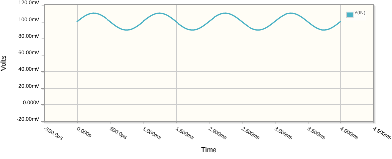
That formula in the book is referring to small signals, small AC variations on top of (superimposed onto) a steady DC potential. So, if you image that you have an average DC potential across the diode of 0.1V, to bias the diode, that might be written \$V_{BIAS}=0.1V\$, and superimposed onto that you have a very small (in comparison to \$V\$) sinusoidal voltage, a "signal" \$v_{SIG}\$ of amplitude 10mV. The expression describing the combined signal \$V\$, as it varies over time, might be written:

$$ V = V_{BIAS} + v_{SIG}sin(\omega t) $$

In the following graph of V against time, you can see the DC offset \$V_{BIAS}=+0.1V\$ as its average value above the x-axis, and \$v_{SIG}=0.01V\$ is the amplitude of the small sinusoidal fluctuations above and below that average:
enter image description here

In that example \$v_{SIG}=0.01V\$ may not be considered "small", but I had to make it significant enough to see the principle at work in the graph. In the context of this question "small" means much smaller than this, and in the context of simulation and "small signal AC analysis" it means infinitesimally small.

To reiterate the most important point, small \$v\$ refers to the amplitude of the AC component of the waveform, not to any absolute value at any particular instant in time.

You may have already figured out where this is going, but I'll continue.

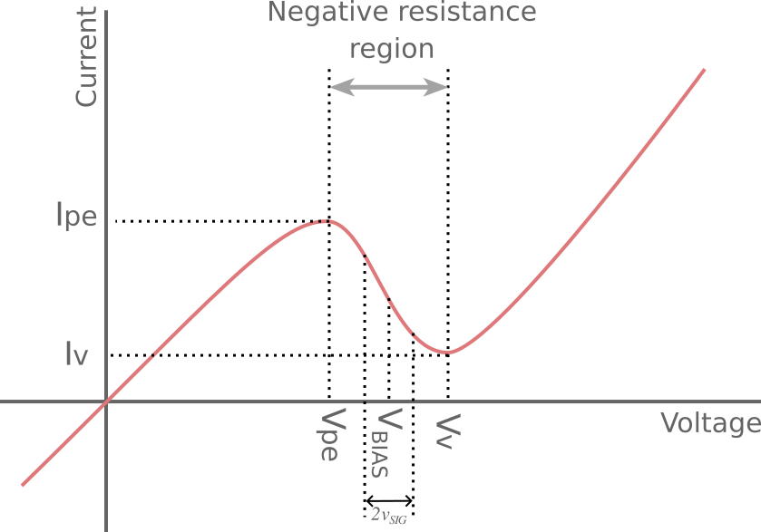
Let's take a look at a tunnel diode's VI curve, which I borrowed from www.electronics-notes.com, and then annotated a bit:
enter image description here

The region of interest is between \$V_{pe}\$ and \$V_V\$, which are actual potentials, not amplitudes. In this region, as voltage rises current falls, and the diode behaves as if it had negative resistance. That resistance will be calculated as the run-over-rise slope in that region, and we will bias the diode at some point near the middle of that region, at \$V_{BIAS}\$.

As long as the voltage \$V\$ across the diode does not deviate far from \$V_{BIAS}\$, meaning that whatever signal we superimpose onto \$V_{BIAS}\$ does not cause us to leave that region (in other words, its amplitude \$v_{SIG}\$ is small, compared to \$V_V-V_{pe}\$), then the diode will behave as if it were a negative resistance.

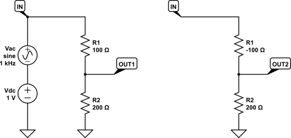
Below left is a simple resistive potential divider, with two positive resistances, and on the right I've replaced R1 with a negative resistance.
schematic

simulate this circuit – Schematic created using CircuitLab

Obviously the left-hand "normal" circuit has the the following relationship between \$V_{IN}\$ and \$V_{OUT1}\$:

$$ V_{OUT1} = V_{IN}\frac{R_2}{R_2+R_1} $$

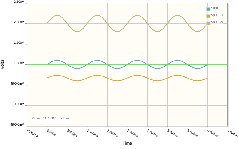
You might be surprised to learn that the right hand circuit, with that negative resistance, has the exact same relationship between \$V_{IN}\$ and \$V_{OUT2}\$. Here are those relationships plotted, with \$V_{IN}\$ blue, \$V_{OUT1}\$ in orange, and \$V_{OUT2}\$ in tan:
enter image description here

The important take away here has nothing to do with the instantaneous values of any waveform, it's all about the relative amplitudes of them. That negative resistance is clearly causing the circuit to produce an output with greater amplitude than the input.

Obviously you couldn't build this second circuit with any real-life resistors, since negative resistors don't exist. You could build an active module using op-amps, to emulate a negative resistance, though, and you'd see this same result.

In the relationship

$$ V_{OUT2} = V_{IN}\frac{R_2}{R_2+R_1} $$

if the denominator is larger than the numerator here (as is the case when both resistances are positive), this represents attenuation. If R1 is negative, though, the denominator can be smaller, causing amplification. In the graph you can clearly see that the amplitude of the sinusoidal part of \$V_{OUT2}\$ is greater than that of \$V_{IN}\$.

We are relating instantaneous values of \$V_{OUT2}\$ with a corresponding (in time) instantaneous value of \$V_{IN}\$, and you can see proportionality between \$V_{OUT2}\$ and \$V_{IN}\$. That is, if \$V_{IN}\$ doubles, then so does \$V_{OUT2}\$. In other words, the gain \$\frac{R_2}{R_2+R_1}\$ is constant.

Therefore we can also say that a change in \$V_{IN}\$ will also result in a proportional change in \$V_{OUT2}\$, by the same factor. Let's rewrite the input as a combination (sum) of some DC offset potential \$V_{IN(DC)}\$ and a small sinusoidal component \$V_{IN(AC)}\$, assuming that the DC part remains constant:

$$ V_{IN} = V_{IN(DC)} + V_{IN(AC)} $$

Do the same for output \$V_{OUT2}\$:

$$ V_{OUT2} = V_{OUT2(DC)} + V_{OUT2(AC)} $$

Now we can plug these into the relationship above:

$$ V_{OUT2(DC)} + V_{OUT2(AC)} = (V_{IN(DC)} + V_{IN(AC)})\frac{R_2}{R_2+R_1} $$

Expand and rearrange to leave only \$V_{OUT2(AC)}\$ on the left:

$$ V_{OUT2(AC)} = V_{IN(AC)}\frac{R_2}{R_2+R_1} + \overbrace{V_{IN(DC)}\frac{R_2}{R_2+R_1} - V_{OUT2(DC)}}^\text{Constant DC offsets} $$

Notice that, as long as we keep all DC components constant, the last two terms on the right are constant values, and can be replaced by an arbitrary, unchanging value \$V_{OFS}\$. In practice this constant accounts for diode biasing and whatever other DC offset potentials are present:

$$ V_{OUT2(AC)} = V_{IN(AC)}\frac{R_2}{R_2+R_1} + V_{OFS} $$

Now \$V_{IN(AC)}\$ and \$V_{OUT2(AC)}\$ are the "signals" of interest, the small fluctuations in input and output potential, and according to this last equation, output fluctuations are a factor of \$\frac{R_2}{R_2+R_1}\$ different from the input.

To paraphrase that, input and output amplitudes are related by that factor. We may write:

$$ v_{OUT2} = v_{IN}\frac{R_2}{R_2+R_1} $$

where \$v_{IN}\$ and \$v_{OUT2}\$ are amplitudes. Otherwise put, we are simply saying that the amplitudes of the AC components are also proportional, and the constant of proportionality is the gain of the potential divider \$\frac{R_2}{R_2+R_1}\$. However, in doing so, we can no longer infer anything about the actual instantaneous potentials, or DC offsets, only their relative amplitudes.

Anyway, since R2 is to be replaced by a tunnel diode, what you now have is a an element that exhibits a negative resistance. We have been very careful to choose all DC offset potentials and potential differences in the circuit to ensure that the diode is squarely "positioned" (biased) in that region of negative resistance, where an increase of voltage across it will result in a decrease of current through it.

We then make the assertion that we won't apply (superimpose) any potential change large enough to exit that region, that all potential changes will be "small", which is another way of saying our AC signals will have small amplitude, and the DC potentials will remain steady. If we replace \$R_1\$ with \$r_t\$, the diode's effective "small signal AC" resistance in that region, the following relationship remains true:

$$ v_{OUT2} = v_{IN}\frac{R_2}{R_2+r_t} $$

Since \$r_t\$ is negative, the denominator is smaller, and there is amplification.

\$\endgroup\$
1
  • \$\begingroup\$ Actually, I realise I have not justified how I can simply replace R1 with \$r_t\$. I'll do that when I have some time. \$\endgroup\$ Commented Mar 3, 2023 at 8:02
1
\$\begingroup\$

The mystery of negative resistance

There is hardly any other such circuit phenomenon as the negative (differential) resistance which seems so complex and mysterious but at the same time is so intuitive and easily explained. This contradiction between the complex way in which it is presented and its simple essence led me years ago to dedicate a detailed Wikibooks story to it. Now, with the help of CircuitLab, I will demonstrate in practice the simple idea behind this phenomenon.

Basic idea

It can be expressed with only one word - dynamization, in its two related implementations - dynamic resistor and dynamic voltage divider. Specifically, the negative differential resistor is actually a "positive resistor" that changes its resistance simultaneously with the input voltage; thus it creates the illusion of "negative resistance". For example, the tunnel diode increases its resistance when the voltage across it increases so the current through it decreases and it has an N-shaped IV curve (in contrast, a neon lamp decreases its resistance and it has an S-shaped IV curve).

Implementation

First, I will show how, with the help of CircuitLab, we can emulate a negative resistor and then we can use it to make an amplifier. This will be a manually-controlled negative resistor that we can call a "negative resistor man" after the "transistor man" described in The Art of Electronics.

I will use the following procedure: in CircuitLab, I will first set the input voltage rise and then increase the resistance of the variable resistor R until the current decreases to the right degree (i.e., I will set the expected output quantity by adjusting the input quantity).

Dynamic resistor

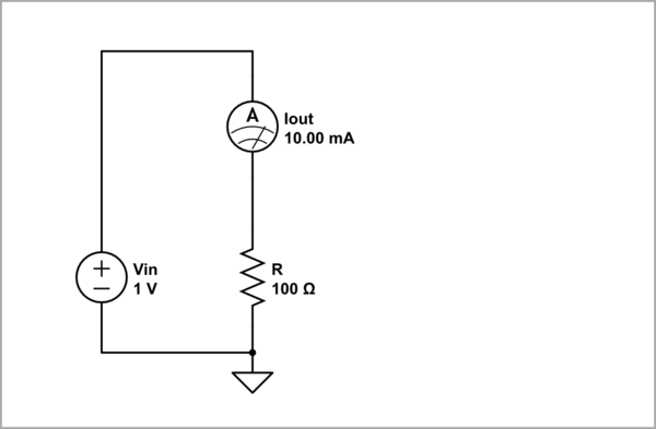
STEP 1: Apply a 1 V input voltage across 100 ohm "static" (constant) resistor R. As a result, according to Ohm's law, 10 mA current flows through the resistor. This point (1 V, 10 mA) is where the phenomenon of negative resistance begins.

schematic

simulate this circuit – Schematic created using CircuitLab

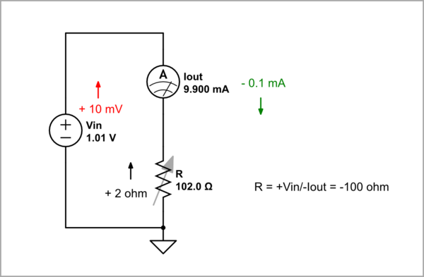
STEP 2: Increase the input voltage with 10 mV and then, to obtain a negative resistance of -100 ohm, begin increasing the resistance of the variable resistor R until the current decreases with 0.1 mA. As you can see from the simulation, the "positive" resistance is 102 ohm but the input voltage source "sees" a negative resistance of -100 ohm.

schematic

simulate this circuit

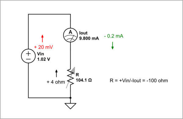
STEP 3: Increase the input voltage with 20 mV and begin increasing the resistance of the variable resistor R until the current decreases with 0.2 mA. The resistance is 104.1 ohm but the input voltage source "sees" again -100 ohm.

schematic

simulate this circuit

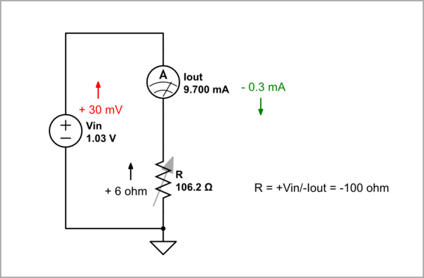
STEP 4: Increase the input voltage with 30 mV and begin increasing the resistance R until the current decreases with 0.3 mA. The resistance is 106.2 ohm but as above, the input voltage source "sees" -100 ohm.

schematic

simulate this circuit

Thus we investigated four points of the negative resistance IV curve determining the values ​​of the current (positive) resistances. If we are patient enough, we can go further and get the rest of the points as well.

Dynamic voltage divider

Now let's make an amplifier by a dynamic voltage divider. For this purpose, we replace the constant resistor R2 in the ordinary voltage divider with a dynamic (negative) resistor. I will use the following procedure: in CircuitLab I will first set the input voltage increase (as above) and then increase the resistance of the variable resistor R2 and accordingly, the divider's transfer ratio, until the voltage decreases to the desired degree (e.g., 2 times). Thus we will obtain an amplifier with a gain of 2.

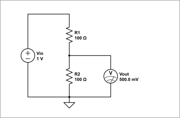
STEP 5: Assemble a voltage divider by connecting two 100 ohm resistors - constant R1 and variable R2, in series. After applying a 1 V input voltage to the divider, 0.5 V voltage appears across the resistance R2. (1 V, 0.5 V) is the initial point of the amplifier transfer characteristic where the phenomenon of negative resistance begins.

schematic

simulate this circuit

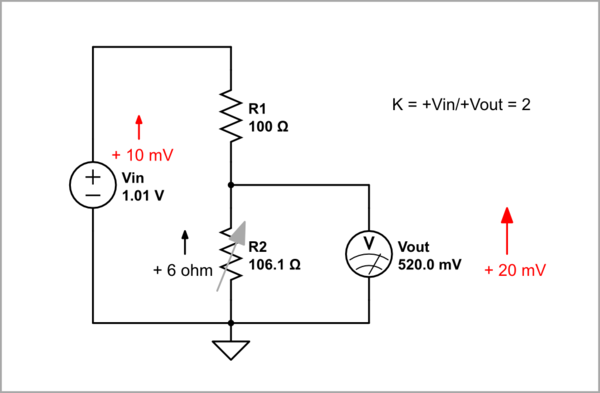
STEP 6: Increase the input voltage with 10 mV and then begin increasing the resistance of the variable resistor R2 up to 106.1 ohm until the output voltage across R2 increases two times (with 20 mV). As a result, we have obtained an amplifier with a gain of two.

schematic

simulate this circuit

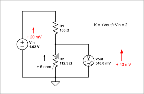
STEP 7: Increase the input voltage with 20 mV and begin increasing the resistance R2 up to 112.5 ohm until the output voltage across R2 increases two times (with 40 mV). As a result, it is an amplifier with a gain of two.

schematic

simulate this circuit

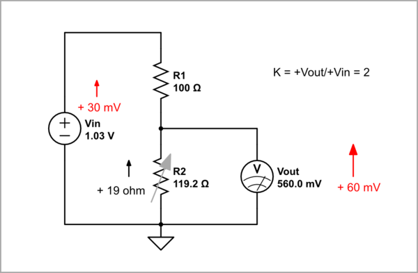
STEP 8: Increase the input voltage with 30 mV and begin increasing the resistance R2 (up to 119.2 ohm) until the output voltage across R2 increases three times (with 60 mV). As above, it is an amplifier with a gain of two.

schematic

simulate this circuit

As above, here we investigated four points of the voltage divider's (tunel diode amplifier's) transfer ratio. We can go further and get the rest of the points as well.

Of course, in all the simulation experiments above, it would be nice if the resistance could somehow change simultaneously with the voltage; then a DC sweep can also be done. I don't know if there is such an option in CircuitLab.

But still, how can a voltage divider amplify?

The trick here is that both the input voltage and divider' transfer ratio change in the same direction. For example, if Vin increases, R2, K = R2/(R1 + R2) and accordingly Vout increase as well. As though the dynamic resistor (voltage divider) "helps" the input voltage source and the output voltage becomes greater than the input voltage (there is a gain).

In fact, the voltage divider has two transfer ratios - static and dynamic. The former is always less than one, but the latter can be greater than one.

\$\endgroup\$
2
  • 1
    \$\begingroup\$ Thx for such a good answer. I never thought about it this way. Thanks again. \$\endgroup\$
    – G36
    Commented Mar 4, 2023 at 12:58
  • \$\begingroup\$ @G36, Thank you so much! Your reaction means a lot to me. I still think I didn't say it clearly enough and I still need to revise it... \$\endgroup\$ Commented Mar 4, 2023 at 15:34

Your Answer

By clicking “Post Your Answer”, you agree to our terms of service and acknowledge you have read our privacy policy.

Not the answer you're looking for? Browse other questions tagged or ask your own question.