1
\$\begingroup\$

I want to implement a boost converter using a MC34063A. I have made the circuit as it is mentioned for step-up operation in the MC34063A datasheet. The datasheet says it can take up to 40V input. But I can see that the IC is getting burnt as soon as my input voltage exceeds 12V. What could be the reason? Here is a schematic of the circuit I'm using:
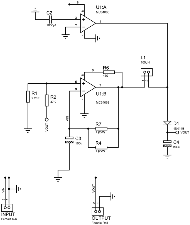
I am attaching the circuit diagram.

A 170uH was not available, that's why I used 100uH instead. Instead of a 0.22 ohm resistor I used 0.5 ohm by paralleling two 1 ohm resistors. Due to the unavailability of a 1500pF capacitor I used 1000pF.

The Schottky diode 1N5819 was not available in Proteus, that's why I have drawn the circuit with a 1N4148, but I am actually using a 1N5819 as suggested in the datasheet. Are these differences affecting the performance of the circuit?

However,after reading a comment,below I have given the circuit using the original model or MC34063 in proteus.
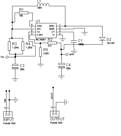
enter image description here

\$\endgroup\$
3
  • 1
    \$\begingroup\$ do you have EXACT circuits for your implementation? \$\endgroup\$
    – user16222
    Commented Oct 26, 2013 at 19:57
  • \$\begingroup\$ either the data sheet is wrong or your circuit is wrong. I can read the data sheet but I have no idea what you have done so help me out with a diagram. \$\endgroup\$
    – Andy aka
    Commented Oct 26, 2013 at 20:33
  • \$\begingroup\$ I have attached the circuit.Plz take a look. \$\endgroup\$
    – A.R
    Commented Oct 27, 2013 at 7:45

2 Answers 2

2
\$\begingroup\$

I'm going to necro this thread, because I had a similar problem and it may be useful to anyone googling it.

My application did not have any current limiting hardware; this one should. But the possibility exists that the series inductor value is lower than expected, which would allow an unusual amount of current through the onboard switch.

To find out, you could use external switching transistors that can handle it, in a cascode configuration. Or, a gate driver IC and a Mosfet.

If the controller IC still burns out after that, you may have a bad batch of controllers. This happened to me recently, where the ICs I had ordered had been damaged at the warehouse.

\$\endgroup\$
5
  • \$\begingroup\$ What about L1, the 100uH inductor, is it saturated? If not, the cycle-cycle current would only be about 3A. What about current limit with 0.5Ohms? Peak current should be limited to about 600mA. \$\endgroup\$
    – user16497
    Commented Apr 29, 2014 at 23:45
  • \$\begingroup\$ Not my thread and its kinda old. But at the instant the switch turns on there are 12 volts only resisted by that half an ohm. This design burns up when it gets turned on. I used a similar design with 10k resistors, so I could use that output to run a driver IC. \$\endgroup\$
    – user39962
    Commented Apr 29, 2014 at 23:54
  • \$\begingroup\$ I understand that you are trying to answer an old question. But, you state that 12V gets shorted to ground through 0.5 Ohms, when actually there is also an inductor there to provide higher impedance at the switching frequency. And there's current limit in the chip. I'm saying that generally with those things in place there is no reason for to the chip to fail by switch over current. There would have to be something else. \$\endgroup\$
    – user16497
    Commented Apr 30, 2014 at 0:48
  • \$\begingroup\$ @gsills, you know what, you're absolutely right. My experience applied to a device with no such limiting function. My answer is totally invalid for this application and I will edit it shortly point this out. \$\endgroup\$
    – user39962
    Commented Apr 30, 2014 at 1:32
  • \$\begingroup\$ I think this is a hard question to answer. Especially since the OP seems to not be around. \$\endgroup\$
    – user16497
    Commented Apr 30, 2014 at 2:16
0
\$\begingroup\$

That looks like no MC34063 that I know of. Your circuit diagram shows two opamps. The MC34063 has a drive transistor, an input comparator, and a timing circuit.

The built-in switch in the 34063 supports at most 1.5A of current, and will be pretty hot when running that much, btw.

Finally, your 'pin 8' at the top of the schematic doesn't even have a label. Where does that go? Who knows?

Draw a real schematic with the actual circuitry of the 34063, and you may get better help. At a minimum, a square with labels for the various pins (rather than just pin numbers) would be a good start.

\$\endgroup\$
2
  • \$\begingroup\$ Jon, it's probably my IE browser, but can you see a circuit diagram in the question? I can't!!! \$\endgroup\$
    – Andy aka
    Commented Oct 27, 2013 at 22:43
  • \$\begingroup\$ pin 8 is connected to pin1 of the inductor. The dual op amp in my ckt,and real MC34063 has the same PCB package DIL08 and I have tested the circuit in real life.so,redrawing the ckt with real MC34063 will not help I guess. However,I will give a try. \$\endgroup\$
    – A.R
    Commented Oct 28, 2013 at 6:37

Your Answer

By clicking “Post Your Answer”, you agree to our terms of service and acknowledge you have read our privacy policy.

Not the answer you're looking for? Browse other questions tagged or ask your own question.