2
\$\begingroup\$

I feel kind of stupid asking this question, but after unsuccessfully searching for papers and then starting to draw my own solution with a lot of XORs to the following problem, I started wondering about how fundamental the problem was, and that literature must already have an solution:

Imagine you have got two controllers, one being a master and one being a slave. Some outside power can tell the slave to be the master at any time, e.g. when the current master is unreachable. As both controllers are connected to some actuator there must be some kind of safe form of mutual exclusion that prevents all foreseeable error scenarios. To accommodate for loss of power or the current master not reverting his master status after a new master was crowned (e.g. if it never received that information) I tought about letting each controller produce additional output signals, e.g. signaling that the controller is the master, and mixing them between logical 0 and 1 (to filter some illegal constellations e.g. 1 & 1 which may be produced through short circuits and the like, or 0 & 0 in case of power loss). These addional signals should then determine which signal path (the actual control signal for the mutually exclusivly accessed actuator) should be blocked and which one shall let the signals pass.

Is there a name for such mechanisms and are there any good papers describing these methods / exclusive access strategies?

\$\endgroup\$
8
  • \$\begingroup\$ See e.g. the Space Shuttle multiple computer systems, "quorum" systems, "high availability" in general, and "STONITH". \$\endgroup\$
    – pjc50
    Commented Oct 29, 2013 at 16:39
  • \$\begingroup\$ Thanks, I'm really just interested in the part close to the actuator with really simple logic that can be fully implemented in very secure hardware, e.g. only a few XOR switches. I've got solutions for the higher level system stuff, I just need some kind of simple hardware-based exclusive access building block. The search terms lead me to system aspects of failsafe systems but not to actual hardware solutions. \$\endgroup\$ Commented Oct 29, 2013 at 16:43
  • \$\begingroup\$ The STONITH expression sounds great (in the sense of funny), never heard of that :-) \$\endgroup\$ Commented Oct 29, 2013 at 16:50
  • \$\begingroup\$ For true redundancy surely you need multiple actuators; after all, the mechanical part is the most likely to fail. For selecting between control signals, perhaps a relay with each control node having one end of the coil, like an H-bridge? \$\endgroup\$
    – pjc50
    Commented Oct 29, 2013 at 16:57
  • \$\begingroup\$ Thanks, I'm actually okay with mechanical parts failing, as long as the degrade in a specific manner, I just want to prevent unforseable errors when both controls give the actuator different commands. \$\endgroup\$ Commented Oct 29, 2013 at 17:04

1 Answer 1

1
\$\begingroup\$

Mutual exclusion is a pretty common term for this concept. IBM has a patent on a more complex concept related to the use of mutually exclusive redundancy in a plural "voting" context for error detection. This concept also frequently finds use in the context of functional safety standards, such as IEC 61508 or ISO 26262.

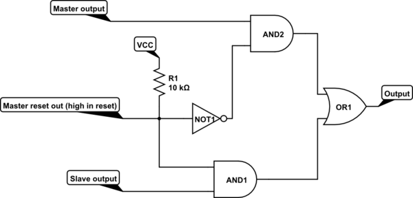
There are no doubt more elegant ways to solve (or optimize) it, but this is a fairly straightforward solution that prevents the master and slave from having simultaneous control.

schematic

simulate this circuit – Schematic created using CircuitLab

\$\endgroup\$
3
  • \$\begingroup\$ Thanks. As I'm not from the electrical engineering domain, I've still got a few questions :-) Is the input at the reset port suposed to be zero all the time (no voltage), and some constant low voltage if a reset shall occur? Who triggers that reset port? How can I simulate this (DC, DC sweep, time domain)? What type of simulation is needed? Do I have to add logical 0 and 1s bevor the input nodes to get a simulation? Can the master and slave input be any kind of signal e.g. modulated, constant voltage? Thanks so much. \$\endgroup\$ Commented Oct 30, 2013 at 9:06
  • \$\begingroup\$ Some microcontrollers will either push a certain pin high or open a drain when operational, in which case a pull-down or pull-up can be used in the non-operational state to achieve the opposite level, giving a good indication of the operational status of the micro. Other micros have an output that indicates whether the micro is in a (powered) reset state. Even without dedicated functionality, this could be accomplished with a GPIO that is set high or low at startup (to deal with an active-low reset signal, just move the NOT gate to the other AND gate and change the pull-up to a pull-down). \$\endgroup\$ Commented Oct 30, 2013 at 18:48
  • \$\begingroup\$ In essence, the circuit above is a simple 2x1 multiplexor, where the "Master reset out" line is the select input. The master and slave signals can indeed be anything you want, within the bounds of whatever digital logic constraints you define for the system. As for simulation, I'm not the most qualified person here to answer that one, so I'll refrain from muddying the waters with an attempt. \$\endgroup\$ Commented Oct 30, 2013 at 18:52

Your Answer

By clicking “Post Your Answer”, you agree to our terms of service and acknowledge you have read our privacy policy.

Not the answer you're looking for? Browse other questions tagged or ask your own question.