What is going to be the voltage on the secondary terminals of the transformer?
If the transformer has a 1:1 winding ratio, then the primary voltage equals the secondary voltage at all times (neglecting leakage and other non-ideal stuff). In the more general case, the voltage ratio between the primary and secondary sides is equal to the the winding ratio.
Will we be also transmitting a ground reference to the receiving end? Or, it will just be a pair of differnetial signals?
If the receiving end is connected to the secondary, and you don't otherwise connect the secondary to ground, then there's no ground reference. That's often the point of using transformer-coupled signaling.
do we always need a reference voltage when we send a differential signal? If not then how does the receive end knows the reference voltage?
The "reference" is the other half of the differential pair.

simulate this circuit – Schematic created using CircuitLab
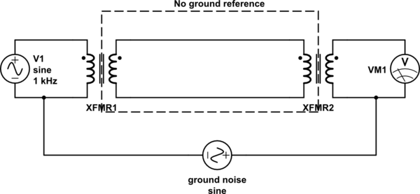
Here, VM1 will mirror V1, even if the two sides are connected to different grounds. The ground noise, which might represent natural variations in Earth potential between two distant points, has no effect on the signal. For signal transmission across appreciable distances, this is a really big win.
I've drawn it here with two transformers to make it symmetrical, and so you can clearly see how there's a loop of wire in the middle with no connection to anything else, but which caries the signal anyway. However, even with one transformer, the ground noise is still isolated, although each side is referenced to its own, different idea of "ground".

