2
\$\begingroup\$

My textbook is trying to explain why adding in a dielectric between two conductors causes a change in the field inside. They provide the following image:
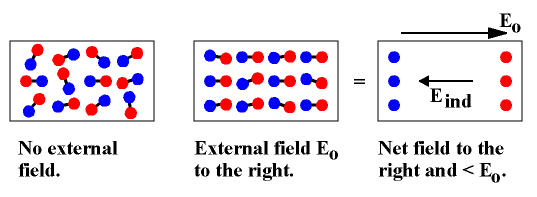
illustration of electric dipoles

I don't understand how the second image is equal to the third image. Why does polarization and alignments of the molecules create an electric field in the shown direction?

\$\endgroup\$

3 Answers 3

3
\$\begingroup\$

The end is the net result. The blue and red dots in the middle of the second diagram "cancel out", so to speak. This results in the third diagram being an accurate model of the real physical situation in the second diagram.

\$\endgroup\$
4
  • \$\begingroup\$ I don't understand what you mean by cancelling out. If all the red and blue dots cancel out with the other dot in the pair, you end up with nothing! Plus theres a distance between them so they can't cancel out since there not at the same location. \$\endgroup\$
    – dfg
    Commented Feb 5, 2014 at 16:56
  • \$\begingroup\$ The ones which cancel are the pairs without the line between them. This leaves you with only the dots on the edges. \$\endgroup\$
    – SomeEE
    Commented Feb 5, 2014 at 17:01
  • \$\begingroup\$ Also, I am not making any statements about physics just about what the diagram is intended to communicate. \$\endgroup\$
    – SomeEE
    Commented Feb 5, 2014 at 17:03
  • \$\begingroup\$ But why would they cancel out with the ones that they are not connected to instead of the ones they are connected to? \$\endgroup\$
    – dfg
    Commented Feb 5, 2014 at 17:26
0
\$\begingroup\$

Each of the red-blue pairs connected by a line is an electric dipole. The positive and negative poles of each dipole are separated by a small distance, and consequently, they have a small moment.

The fields of each of these little dipoles add together, and to simplify analysis we can think of these little dipoles as a smaller number of bigger dipoles with a greater moment. This is illustrated in the rightmost image as the red and blue dots being separated by a greater distance.

\$\endgroup\$
0
\$\begingroup\$

Your main question is answered by @MathEE. But the blue and red dots in the last diagram should probably be bigger or of a different color to show that the total effect is not the same as looking at the ends (otherwise the thickness of dielectric would not matter). In the dielectric material the molecules are pretty much randomly oriented. When the electric field is applied, it takes energy to twist those molecules in one direction (the field does work on the dielectric), fighting against the local electric fields of the molecules they are near. This reduces the electric field and more charge is needed to keep the electric field constant - assuming the cap is connected to a voltage source. This energy is released when the field changes. This is how a dielectric increases the capacitance between plates of a capacitor. Instead of just energy storage in the electric field you get some stored mechanically like compressing a spring. In electronics texts the whole effect is treated using the the surface charge of the dielectrics rather than going through integrating the electric field in the dielectric.

\$\endgroup\$

Your Answer

By clicking “Post Your Answer”, you agree to our terms of service and acknowledge you have read our privacy policy.

Not the answer you're looking for? Browse other questions tagged or ask your own question.