I am trying to design an Oscillator circuit which can produce a good sine wave with a frequency of at least 500 Mhz. This is for RFID applications. I have tried to use an class E oscillator, but i cant seem to get the design right. Can anyone help me out?
-
\$\begingroup\$ What circuit did you try? We have a schematic editor, you can launch it on the edit post page with Ctrl-M. \$\endgroup\$– user17592Commented Apr 14, 2013 at 18:54
-
\$\begingroup\$ What have op amps got to do with it? They aren't used in UHF oscillators. \$\endgroup\$– Leon HellerCommented Apr 14, 2013 at 19:09
-
\$\begingroup\$ You could simply use OP-Amps to generate a low frequency less than 10KHz and use a frequency multiplier. \$\endgroup\$– Standard SandunCommented Apr 14, 2013 at 19:26
-
2\$\begingroup\$ From 10 kHz to 500 MHz? You are joking? \$\endgroup\$– Leon HellerCommented Apr 14, 2013 at 19:59
-
\$\begingroup\$ @sandundhammika I'd be curious to know of any realistic stability feasible for a frequency multiplier of 50,000 x. \$\endgroup\$– Anindo GhoshCommented Apr 15, 2013 at 6:14
1 Answer
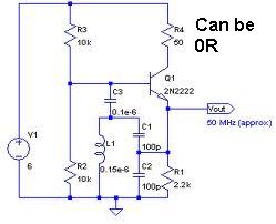
I'd use a colpitts oscillator. In fact i've just been designing one at 250MHz. Here's the general design: -

The diagram shows a 50MHz oscillator but if you use a high-speed transistor that has an Ft of 5GHz or above you'll get decent results at 500MHz. If you want it to work at 3V3 make R3 = 2k2 and R1 = 1k. I'm trying to remember the transistor I used - it was from NXP - it'll come to me later..... BFR42A!!
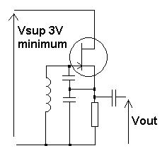
JFET colpitts (even simpler): -

The JFET to try is a BF545B. It should work at 3V3 but don't load it too much. The cap on the gate would be about 4p7 and the cap across the source resistor would be about 10pF. Inductor about 12nH. You need a JFET with V(th) less than 3V for it to oscillate. The output was through a 2pF to a common emitter circuit using a BFR42A. If you are lightly loading it you'll get away without the 2nd stage. The sinewave purity was very good but still would need another 20dB of attenuation at the 2nd harmonic for it to be reasonably pure. The source resistor was about 1k5 but this depends lot on the jfet you choose. It's always amazed me how much simpler these circuits are compared to BJT's - no bias resistors - the JFET biases itself thrugh the voltage developed across the source resistor and the fact that the inductor keeps the gate at 0V. Anyone remember valves?
Both designs can be tuned with a varactor diode and that can also be used for FM data modulation. To keep it in tune I have used an ADF4111 around it. It's a PLL and needs a couple of registers setting up with a PIC or similar.
