15
\$\begingroup\$

I think I know how to do this, but you can find a lot of different instructions and calculators online that contradict each other. I have yet to find a clear, concise procedure for calculating the self-noise of op-amp circuits (including thermal noise, shot noise, etc., but not including interference from external sources), and one of the sources many people cite apparently has a number of errors, so I'll ask it here and see who can explain it best.

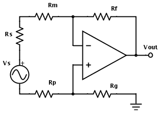
For example, how would you calculate the output noise of this circuit?

A differential op-amp circuit

Which noise sources do you include?

  • Op-amp internal input voltage noise
  • Op-amp internal input current noise
  • Resistor thermal noise
  • Op-amp output stage noise?

How do you calculate each component's contribution? How do you combine the noise components together? What gain do you use to get the output noise from the input equivalent noise? How do you calculate the gain? Is it the same as the signal gain? What kind of simplifications and shortcuts can be made and how different will the result be from the real world?

etc. etc. etc.

\$\endgroup\$
0

2 Answers 2

7
\$\begingroup\$

The question which noise sources need to be taken into consideration depends on how severe they are. Your question indicates that you are interested in noise generated at the op amp and not noise generated by interference from neighboring circuits (internal/external noise).

In order to make things comparable, all noise is referred to the op amp's input (RTI). In theory, I guess any point in your circuit might work as long as you refer all noise sources to that point, but it is common practice to act as if all noise sources were directly at the input pins. Sources include noise in the resistors, noise generated by current flowing into the op amp's input pins and noise that may be considered as a voltage between the inputs pins.

There is a very good discussion at this Q&A-style source and also in this nice article from 1969 (!), both authored by Analog Devices' staff.

Without re-typing everything in these sources, here are some rules of thumb:

Noise in the resistors becomes bad when the resistor values are high (some 100k or some 1M) and when the circuits are designed for high bandwidth since the noise is proportional to \$ \sqrt{4k \cdot T \cdot B \cdot R}.\$

You can try to minimize R, you can try to limit the bandwidth B if possible, you can put the circuit in liquid nitrogen (low temperature T), but you can't go for a low Boltzmann constant, because Boltzmann is dead (quote stolen at Analog Devices).

Current noise, i.e. noise generated by current flowing into the op amp inputs, will be converted to a noise voltage by the resistors around the input (\$R_f\$, \$R_g\$) and amplified by the circuit's gain. This is one of the reasons why one prefers op amps with very low input currents especially for high-ohmic circuits.

Voltage noise results from a real op amp's inability to completely null the voltage between the input pins.

All noise sources can be combined as the square root of the sum of their squares since they are independent of each other, which will work only if all sources are RTI.

\$\endgroup\$
3
  • 1
    \$\begingroup\$ +1 for "Boltzmann is dead", however cold it sounds. \$\endgroup\$
    – tyblu
    Commented Apr 11, 2012 at 3:29
  • 2
    \$\begingroup\$ The individual noise sources have to be combined as the square root of the sum of their squares since they are independent of each other. \$\endgroup\$
    – Barry
    Commented Nov 7, 2012 at 22:41
  • \$\begingroup\$ @Barry - Thanks, I have edited your correction into the answer. \$\endgroup\$
    – zebonaut
    Commented Nov 8, 2012 at 8:28
4
\$\begingroup\$

OK, I know how to do this now.

There are 3 main sources of noise that need to be calculated:

  • Thermal noise of the resistors themselves
  • Voltage noise of the op-amp itself
  • Current noise of the op-amp, which interacts with the resistors to produce a voltage noise

So first, you want to find the equivalent resistance seen from the inputs of the op-amp looking outward into the circuit, with voltage sources (such as the op-amp output) set to 0 V (equivalent to converting them to short-circuits to ground). For this circuit: $$ R_\mathrm{eq}=(R_\mathrm{m}+R_\mathrm{s}+R_\mathrm{p})\|(R_\mathrm{f}+R_\mathrm{g}) $$
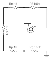
Virtual ohmmeter looking out into the circuit from the op-amp inputs

So for example, if Rs = 100 Ω, Rm = Rp = 1 kΩ, and Rf = Rg = 100 kΩ, then Req = 2.1 kΩ.

To find the thermal noise of this equivalent resistance, use the Johnson–Nyquist formula: $$ v_\mathrm{n}={\sqrt {4k_{\text{B}}TR\Delta f}} $$ There are online calculators to do this for you:

For example, with Req = 2.1 kΩ, at 27 °C, with an audio bandwidth of 22 kHz, the resistors would contribute 0.87 μVRMS = −121 dBV input noise.

Then find the voltage and current noise of the op-amp in the datasheet. Typically:

  • If \$R_\mathrm{eq}\$ is small, you want a BJT-input op-amp, which has lower voltage noise (0.7-5 nV/√Hz), but higher current noise (500-4000 fA/√Hz).
  • If \$R_\mathrm{eq}\$ is large, you want an FET-input op-amp, which has lower current noise (1-10 fA/√Hz), but higher voltage noise (3-15 nV/√Hz).

To convert the spectral density \$\tilde v\$ (in nV/√Hz) to a voltage (in VRMS), you need to multiply it by the square root of the bandwidth: $$ v_\mathrm{RMS}=\tilde v \cdot \sqrt{\Delta f} $$ So for example, if the op-amp is a TLC071, with equivalent input noise voltage density of 7 nV/√Hz, the voltage noise of the op-amp contributes 7 nV/√Hz ⋅ √(22 kHz) = 1.04 μVRMS = −120 dBV.

The resistor noise and op-amp noise are similar levels, which means they'll combine to about 3 dB higher, or −117 dBV. To calculate their combination exactly, since they're uncorrelated, you need to use root sum squared: $$ v_\mathrm{total}=\sqrt{{v_\mathrm{R}}^2+{v_\mathrm{OP}}^2} $$ So √(0.872+1.042) = 1.36 μVRMS = −117 dBV, as estimated.

The current noise is probably irrelevant for an FET-input op-amp, so we can skip to calculating the output noise: Just multiply the input noise by the gain of the amplifier. However, you need to multiply by the "noise gain", not the signal gain. To find the noise gain of the amp, convert your existing sources into short circuits and put a test voltage source right in series with the non-inverting input of the amp:
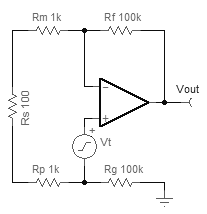
Differential amplifier with noise source in series with non-inverting input for calculating noise gain

So the op-amp will do whatever it takes for the inverting input to equal the non-inverting input. There will be one current path: $$ I=\frac{V_\mathrm{out}}{R_\mathrm{f}+R_\mathrm{m}+R_\mathrm{s}+R_\mathrm{p}+R_\mathrm{g}} $$ and this is related to \$V_\mathrm{t}\$ by: $$ V_\mathrm{t}=I(R_\mathrm{m}+R_\mathrm{s}+R_\mathrm{p}) $$ combining and solving: $$ \frac {V_\mathrm{out}}{V_\mathrm{t}} = \frac {R_\mathrm{f}+R_\mathrm{m}+R_\mathrm{s}+R_\mathrm{p}+R_\mathrm{g}}{R_\mathrm{m}+R_\mathrm{s}+R_\mathrm{p}} $$ So in our case, this is a noise gain of 96.2× = +39.7 dB, and our input noise of −117 dBV becomes −77 dBV at the output. (A TINA simulation gives 137.5 μVRMS = −77 dBV, for comparison.)

More detailed steps

There are several extra steps you can do to make your calculation more accurate:

To calculate the effect of the op-amp's current noise, take the current noise and multiply it by the equivalent resistance calculated earlier. For the TLC071, this is 0.6 fA/√Hz. So, combined with \$R_\mathrm{eq}\$ of 2.1 kΩ, we get 0.00126 nV/√Hz. Obviously this is much smaller than the op-amp's voltage noise, so it will have no effect on the result in this example. In cases with large \$R_\mathrm{eq}\$, it will have an effect. You can calculate it this way and combine it with the other sources as shown above: $$ v_\mathrm{total}=\sqrt{{v_\mathrm{R}}^2+{v_\mathrm{V}}^2+{v_\mathrm{I}}^2} $$ Also likely to have an effect is the bandwidth of your measurement equipment. The previous measurements assume a brickwall filter at 22 kHz, but brickwall filters can't exist in reality. You can correct for the fall-off of a real-life filter by calculating the equivalent noise bandwidth (ENBW). Here's a table of ENBW Filter correction factors vs order. See also Why are there two sets of ENBW correction factors?

In fact, voltage noise of the op-amp is not actually a constant. It varies with frequency, so is better written as \$\tilde v(f)\$. You can calculate it more accurately with numerical integration. See Noise and what does V/√Hz actually mean?
\$\endgroup\$
6
  • \$\begingroup\$ I know this is an old thread, but I am now facing something similar myself. I am confused when you calculated the equivalent resistance in your answer. You say that (m+s+p) are in parallel with (f+g)... would you be kind enough to maybe explain how to see this, or perhaps add a basic equivalent diagram? Are both Rp and Rs shorted to ground, as well as the op amp output, to be able to see this? \$\endgroup\$
    – teeeeee
    Commented Oct 1, 2019 at 11:00
  • \$\begingroup\$ @teeeeee "you want to find the equivalent resistance seen from the inputs of the op-amp looking outward into the circuit, with voltage sources converted to short-circuits (to ground)." \$\endgroup\$
    – endolith
    Commented Oct 1, 2019 at 16:07
  • \$\begingroup\$ @teeeeee in other words, remove the op-amp, place a ground where its output used to be (since that's a controlled voltage source) and then connect a ohmmeter to where the input terminals used to be. Rf will be grounded like Rg is, so they are shorted together \$\endgroup\$
    – endolith
    Commented Oct 1, 2019 at 16:08
  • 1
    \$\begingroup\$ please forgive my struggle with this, but I'm still not seeing it. Do you mean place an Ohmmeter in series with each input, with their negative sides to ground? Or a single one that would be effectively inside the op amp across the pins? Isn't the goal here to calculate the effect the input current noise of the op amp will have? Also, do you remove the voltage source and short it to gnd as well? Maybe a sketch would really help me if you have time. Can you point me to a reference where this technique of adding the Ohmmeter and gnding the output is explained? Thanks for you pateience! \$\endgroup\$
    – teeeeee
    Commented Oct 10, 2019 at 9:21
  • 1
    \$\begingroup\$ @teeeeee Added an image to the answer \$\endgroup\$
    – endolith
    Commented Oct 10, 2019 at 15:07

Your Answer

By clicking “Post Your Answer”, you agree to our terms of service and acknowledge you have read our privacy policy.

Not the answer you're looking for? Browse other questions tagged or ask your own question.