0
\$\begingroup\$

Below schematic is a simplified version of a power supply:
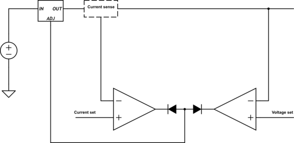
schematic

simulate this circuit – Schematic created using CircuitLab

When the voltage is set to 12V and current limit is set to 100 mA and output is connected to a resistive load (10 ohm), the current pulled from the supply is exactly 100 mA. but when an inductive load is connected (brushless fan) it only pulls 75 mA from the supply.

Why inductive load draws less current when there's room for it to draw more? Is it because of it's inductive properties or I should look for the source of the problem in the circuit?

\$\endgroup\$
15
  • \$\begingroup\$ Why should it take more than 100 mA? It depends on what it is and what it’s effective resistance is. \$\endgroup\$
    – Andy aka
    Commented Jan 24, 2020 at 12:37
  • \$\begingroup\$ Its not it’s, stupid spelling killer. \$\endgroup\$
    – Andy aka
    Commented Jan 24, 2020 at 12:59
  • \$\begingroup\$ @Andyaka not more than 100mA but the actual 100mA. \$\endgroup\$ Commented Jan 24, 2020 at 13:18
  • \$\begingroup\$ How much does it take when the current isn't limited? I bet 75mA. This circuit keeps you from drawing more than 100mA, but it doesn't prevent you from drawing less. Your 10 ohm resistor would draw 1200mA if not current limited to 100mA, but a 160 ohm resistor would draw only 75mA either way. \$\endgroup\$ Commented Jan 24, 2020 at 13:25
  • \$\begingroup\$ @CristobolPolychronopolis it draws ~120mA when current is not limited. \$\endgroup\$ Commented Jan 24, 2020 at 13:32

2 Answers 2

1
\$\begingroup\$

You are detecting Peak current and not Average Current as should be !! Where are your specs????

A BLDC fan acts like a resistive load ONLY when you average the current over a specific time interval such that there is no ripple in the Avg current measurement. As such, the fan current increases linearly with voltage above the start speed due to RPM fan load.

The storage Caps "can" provide most of the ripple current if rated you wanted that otherwise use your regulator for it and define a filter with peak ripple % vs f , as you like.

Yet your current sense amplifies peak pulse current with 10ms average which is too short an Tau or too little attenuation of peak/average current ratio. Therefore you need to know the pulse frequency and filter rejection at that freq to obtain an error of peak to average. Then understand the consequences.

If max RPM is 3600 = 60 Hz and current pulses are 2x = 120 Hz and you want current measured in 100ms to be 1% error max then you need a filter of -40dB at 120 Hz with a group delay of 100ms max.

Are these assumptions acceptable? Do you know how to design a LPF?

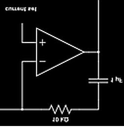
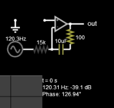
Consider enter image description here instead of your enter image description here

\$\endgroup\$
12
  • \$\begingroup\$ What specs should I add? How can I detect average current? \$\endgroup\$ Commented Jan 24, 2020 at 18:08
  • \$\begingroup\$ You Must Define a LIST of Specs: All Input Ranges , All output ranges. Ripple, Step load Overshoot, Pulse current attenuation % or dB @ freq like any LP filter. Load Regulation Error.% Step Load Error 50 to 100% to 50% I @ TBD % V error. These are your Design Acceptance criteria. Look around at professional PSU Specs. They have more ...but this is minimal. \$\endgroup\$
    – D.A.S.
    Commented Jan 24, 2020 at 18:13
  • \$\begingroup\$ I don't know what most of those are and how to measure it! the input is 24V, for op amps it's +24V/-5V. there's no ripple (as far as my crappy scope can measure) and no over/undershot when going to CC mode or recovering from it and also when turning on/off the PSU. output voltage is 0-20V 1A. \$\endgroup\$ Commented Jan 24, 2020 at 18:27
  • \$\begingroup\$ You don't know I max or Vmin or Ictrl, input? Then you are not ready to design and must go back to reading/learning. Do you know how to define a stepload and measure error? \$\endgroup\$
    – D.A.S.
    Commented Jan 24, 2020 at 18:28
  • 1
    \$\begingroup\$ some day you will do what I suggest. Make specs. Then implement \$\endgroup\$
    – D.A.S.
    Commented Jan 24, 2020 at 20:53
1
\$\begingroup\$

Sorry, but brushless motor is a complex load. It has electronic commutator which switches the input voltage to the winding or windings which currently are best to keep the motor running. The load is not pure inductance, there are controlled switches in series and the controller itself. If your current limiter causes voltage drops they can disturb the controller. Your system can oscillate. If you have an oscilloscope, check does the voltage stay stable. Anything written without having your system is only guessing.

If you have a big inductor, say the secondary winding of a few voltage output AC mains transformer, you can check what pure inductive load causes.

WARNING: removing the DC from the coil by disconnecting a wire causes a disastrous high voltage peak. It can be for ex. 15000 volts and punches the insulation of the transformer. Or something which happens to have contact with the transformer get a fatal shock. Be sure that the wires do not get disconnected nor make bad contact as long as there's power on in the system. If you happen to be a beginner do not try this!

\$\endgroup\$
9
  • \$\begingroup\$ It is oscillating when the fan is connected and is in current limit mode like crazy, so the odd behavior is because of the circuitry inside the brushless fan? \$\endgroup\$ Commented Jan 24, 2020 at 14:48
  • 1
    \$\begingroup\$ It's well possible that a pure inductor also could cause oscillation if the PSU circuitry isn't designed for inductive load. I guess (read GUESS) it's the control circuitry which doesn't stand voltage drops. \$\endgroup\$
    – user136077
    Commented Jan 24, 2020 at 14:53
  • \$\begingroup\$ Can you please direct me to a link or give me a keyword to google on how can I design/improve the PSU to be able to control inductive load as well as resistive load? \$\endgroup\$ Commented Jan 24, 2020 at 14:54
  • 1
    \$\begingroup\$ Start by inserting a diode to the output of the PSU. Let it be in parallel with the load but reversed so that it only sucks the inductive current that the inductor tries to keep on going when PSU's control circuit tries to cut the current off. Check how this power opamp OPA544 is applied. It's designed for driving coils and motors ti.com/lit/ds/sbos038/sbos038.pdf which \$\endgroup\$
    – user136077
    Commented Jan 24, 2020 at 15:14
  • \$\begingroup\$ Thanks, added the schematic to the question. appreciate it if you please take a look at it. \$\endgroup\$ Commented Jan 24, 2020 at 15:28

Your Answer

By clicking “Post Your Answer”, you agree to our terms of service and acknowledge you have read our privacy policy.

Not the answer you're looking for? Browse other questions tagged or ask your own question.