1
\$\begingroup\$

I'm looking for an opamp "voltage clamping" circuit with a +/-12V input and a 0/+5V output.

I mean :
When input < 0V = output stays at 0V
When 0V < input < +5V = output 0 to +5V
When input > +5V = output stays at +5V

Thank you for your help !

\$\endgroup\$
6
  • 2
    \$\begingroup\$ Why did you put the word "precision" in the title? For a real circuit design you need to specify the limits and ranges for all of the these voltages. If the input is 3.10V can the output be 3.20V or 3.15V? If the input is 0V can the output be 0.001V? Is it OK if the output is 0.000V when the input is 0.005V? How fast will the input signal change? What is the load on the output? \$\endgroup\$ Commented Apr 7, 2020 at 18:52
  • \$\begingroup\$ I add the precision word because it's for a synthesiser circuit and for 2V input I need 2V output, for 100mV input a 100mV output and so on. Yes, if the input is 0V it can be 0.001V and it's OK if the output is 0.000V when the input is 0.005V :-) I Don't need an extreme precision. The load is an op amp input. Examples to be clear : -12V input = 0V output / -1V input = 0V output / 0V input = 0V output / 3V input = 3V output / 5V input = 5V output / 5.1V input = 5V output / 12V input = 5V output \$\endgroup\$
    – Synthlink
    Commented Apr 7, 2020 at 19:05
  • \$\begingroup\$ So if the input is 2V, what is the acceptable range of output voltages? 1.999V to 2.001V? 1.9V to 2.1V? You still haven't told us what "precise" means to you. \$\endgroup\$ Commented Apr 7, 2020 at 19:19
  • \$\begingroup\$ 1% précision is ok. \$\endgroup\$
    – Synthlink
    Commented Apr 7, 2020 at 19:37
  • \$\begingroup\$ You need to add all of that information to the question itself. \$\endgroup\$ Commented Apr 7, 2020 at 19:55

3 Answers 3

4
\$\begingroup\$

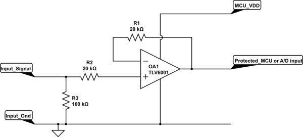
I assume here that you want the 0-5v signal to be processed by an A/D. If you want to protect the input then use a device such as the TLV6001 to buffer the input signals.

A simple circuit such as this will provide accurate translation of the 0-5v signal for any application.
schematic

simulate this circuit – Schematic created using CircuitLab

The TLV6001 is rated for rail-rail operation and so allows the full range of MCU or A/D input ...in addition it is rated to carry 10mA in the input protection diodes. This would allow the configuration above to withstand voltages of +/-200 V on the input resistor R2 (providing your resistors are rated for this voltage).

Since the TLV600 is powered by the MCU +5 V supply it cannot produce an output voltage above 5 V or below 0 V, so the input is accurately clamped WITHOUT impacting the A/D range at all. You must make sure that your MCU solution is always drawing a minimum current greater than your expected protection current (this is only an issue if you put things into a sleep state).

\$\endgroup\$
2
  • \$\begingroup\$ No, it's to control 2164 VCAs thru a log amp circuit. But your idea seems great and inexpensive. And as there's already on my board a +5V ref (with a MAX675) I guess it can power the TLV6001. Thank you very much ! :-) \$\endgroup\$
    – Synthlink
    Commented Apr 7, 2020 at 20:01
  • \$\begingroup\$ Same deal ....above is what you need. \$\endgroup\$ Commented Apr 7, 2020 at 23:30
2
\$\begingroup\$

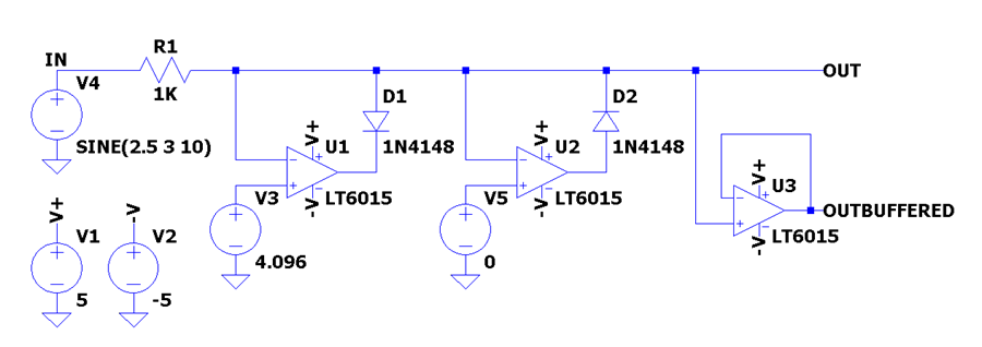
Here is the textbook example: enter image description here Note however, that each opamp is either in saturation (there's a huge differential voltage on inputs when no need for an opamp to clamp) or it tracks its inputs precisely (when it clamps). Therefore, you'll need opamps that are able to switch fast and without ringing from saturation to tracking.
\$\endgroup\$
3
  • \$\begingroup\$ Yes, I've similar schematics in my opamp circuits design books, but I was looking for an inexpensive circuit. Anyway, thank you for your help ! \$\endgroup\$
    – Synthlink
    Commented Apr 7, 2020 at 20:04
  • 1
    \$\begingroup\$ @Synthlink You might want to add inexpensive to the question then. But usually, "precision" and "inexpensive" are not possible at the same time. \$\endgroup\$
    – Justme
    Commented Apr 7, 2020 at 20:10
  • \$\begingroup\$ Yes, sorry, it's the first time I ask for help on this site. Anyway, thank you for your answer ! \$\endgroup\$
    – Synthlink
    Commented Apr 7, 2020 at 20:32
0
\$\begingroup\$

schematic

simulate this circuit – Schematic created using CircuitLab

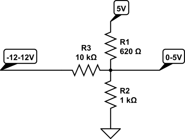
This should work. If you really need to use an op amp, you could buffer the output.

\$\endgroup\$
5
  • \$\begingroup\$ It seems very simple but I guess it won't work in my circuit, because a voltage divider pot is inserted between the input jack and the clamp circuit. If there is nothing wired to the input, or if the input jack is normalised to ground, the output value will not be 0V. But thank you for your idea, I keep it for another design ! \$\endgroup\$
    – Synthlink
    Commented Apr 8, 2020 at 10:15
  • \$\begingroup\$ This circuit will not work, the voltage divider created by R1 and R2 will hold the output at a constant voltage regardless of the input (-12 to 12V). The input voltage is dropped/raised across R3 to match the output voltage determined by the R1/R2 divider which may cause heating problems if too much current flows through R3. \$\endgroup\$
    – soup
    Commented Feb 9, 2022 at 21:45
  • \$\begingroup\$ Did you try deriving a Thevenin equivalent for R1, R2, and 5V? That might make it clearer. \$\endgroup\$ Commented Feb 9, 2022 at 21:49
  • \$\begingroup\$ I didn't (I simulated in LTSpice) and it looks like it led me to a slightly wrong answer, however, this circuit still doesn't achieve what the OP had asked. The output over the -12V to 12V input range is between 2.530V and 3.414V, not the 0 to 5V clamp OP was asking for. That said, if the only purpose was to sample a -12V to 12V input with a lower voltage range ADC (i.e. most ADCs) this circuit is a decent way to do it \$\endgroup\$
    – soup
    Commented Feb 11, 2022 at 17:39
  • \$\begingroup\$ Recalculating, it looks like I miscalculated a couple of years ago. The 10K should have been about 1.8K; maybe I just forgot to change the default value or something. If you throw a 1.8K value on R3, it'll be about as close as you can get with 5% values. \$\endgroup\$ Commented Feb 15, 2022 at 16:56

Your Answer

By clicking “Post Your Answer”, you agree to our terms of service and acknowledge you have read our privacy policy.

Not the answer you're looking for? Browse other questions tagged or ask your own question.