0
\$\begingroup\$

I have this high-pass filter schematic and its AC Sweep simulation. Until the break through the end, the graph is right, but I can't see why the graph breaks on the right hand side and the filter behaves like a band-pass circuit.
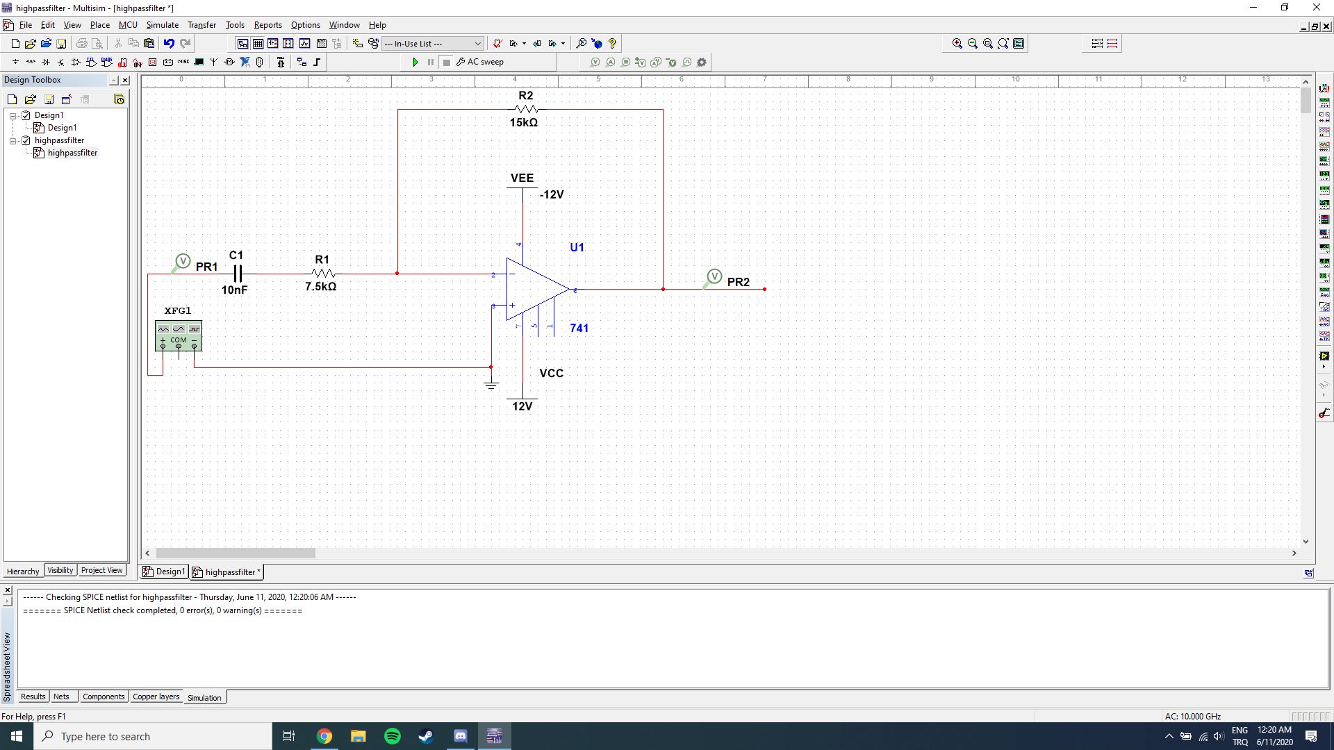
high pass filter schematic

high pass filter ac sweep

\$\endgroup\$
7
  • \$\begingroup\$ It’s probably the 741 you are using. \$\endgroup\$ Commented Jun 10, 2020 at 21:36
  • \$\begingroup\$ Your RC filter corner frequency is Fc = 0.16/(10nF * 7.5k Ohm) = 2.2KHz but your op-amp also does not have an infinite bandwidth. And for the gain of 2V/V the corner frequency for LM741 is F = 1MHz/(2 +1) = 333kHz \$\endgroup\$
    – G36
    Commented Jun 10, 2020 at 21:38
  • \$\begingroup\$ Do you really need a gain of 2 above 1 MHz? Try substituting an op amp that has some gain above 1 MHz (a 741 doesn't). \$\endgroup\$
    – glen_geek
    Commented Jun 10, 2020 at 21:38
  • \$\begingroup\$ mberkkaratas - I have removed your request for members here to contact you by email. If you write a question here, then the question and its answers are public. You can click "follow" below the question, if you want to be notified of every change. In most cases, if someone has a question for you (e.g. a request for further information) you will get a notification in your SE "inbox" and you can setup your profile to send an email 3 hrs later (or daily, or weekly) of those notifications. But if you ask a question, it's better that you check your inbox here very frequently for messages as well. \$\endgroup\$
    – SamGibson
    Commented Jun 10, 2020 at 21:49
  • \$\begingroup\$ The 741 opamp is 52 years old and has a poor high frequency response and trouble with its slew rate above 9kHz. Most modern audio opamps work well up to 100kHz but I have never seen an opamp in a radio frequency circuit. \$\endgroup\$
    – Audioguru
    Commented Jun 11, 2020 at 0:06

1 Answer 1

1
\$\begingroup\$

You’re high pass filter with corner frequency of 1.178khz works well for frequencies under 100khz however as you approach 500khz your gain will drop due to the inherent bandwidth given by the op amp. For a gain of 2V/V and gain bandwidth of 1MHz(for a 741 op amp), you have about 500khz of bandwidth, hence why your voltage gain appears like low pass towards 500khz region and higher. If you choose an op amp with higher gain bandwidth, ie: 10 or 20 MHz or even op amps with 100MHz your circuit will be more like a highpass for higher frequencies. Note that: even with op amps with 250MHz gain bandwidth, you will eventually decrease gain at some point in the upper frequency limit as all op amps have finite bandwidth.

\$\endgroup\$
3
  • \$\begingroup\$ Upvoted. But I have used the same op-amp for low pass and bandpass circuits and it worked ideally on those circuits. I believe it is because of the bandwidth of the selected op-amp. Do you have any suggestions about an op-amp which has a larger bandwidth? \$\endgroup\$ Commented Jun 10, 2020 at 23:01
  • \$\begingroup\$ There’s a couple that I know. OPA365 has gain bandwidth of 50MHz. LT1812 has gain bandwidth of 100MHz, the OPA354 has bandwidth of 250MHz. But these may not meet your supply voltage needs. I recommend checking DigiKey.com and searching on there for what you need. \$\endgroup\$
    – Leoman12
    Commented Jun 10, 2020 at 23:14
  • \$\begingroup\$ "For a gain of 2V/V and gain bandwidth of 1MHz (for a 741 op amp), you have about 500khz of bandwidth," ... Be carefull, don't forget the derating curve due to "slew rate" for large signals ... Bandwith used is for "little signals" ... \$\endgroup\$
    – Antonio51
    Commented Jul 19, 2021 at 14:59

Your Answer

By clicking “Post Your Answer”, you agree to our terms of service and acknowledge you have read our privacy policy.

Not the answer you're looking for? Browse other questions tagged or ask your own question.