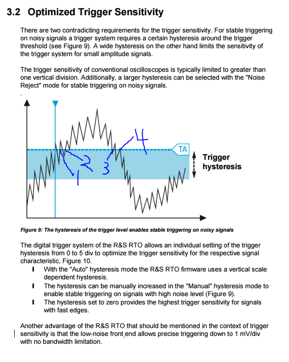
For me, a picture helps explain this best, so I'm going to use Figure 9 from the article that Brian Plummer mentioned, which I've pasted below. (Thanks Brian).
Two Trigger Settings: Holdoff and Sensitivity:
In the world of digital oscilloscopes, getting clean triggers is important, so that you trigger on the signal, where you want to, and not on noise. Two trigger settings are meant to do this: 1) the time (horizontal) "holdoff" setting, and 2) the amplitude (vertical) "sensitivity" setting.
- The holdoff setting says, "don't allow a 2nd trigger event until __ time has elapsed since the 1st trigger event." This prevents unwanted triggers, for example, on subsets of a larger period waveform.
- Ex: you're reading a pulsing square wave signal with repeated short pulses over a 10ms large period. You want to say, "don't trigger on every short pulse; just trigger once per large period." So, set the holdoff to just over 10ms and problem solved: it triggers once per set of short pulses, ie: once per large period.
- The "sensitivity" setting makes up for the trigger sensitivity hysteresis that apparently occurs naturally on analog oscilloscopes. It says, "don't allow a 2nd trigger event until the 1st trigger event is over, and we won't consider the 1st trigger event to be over until the signal goes some vertical distance Y away from the amplitude at which it triggered."
- For a rising edge trigger that occurs at amplitude Y1, this means: "don't allow a 2nd trigger event until the signal falls below (Y1 - sensitivity_value), then rises back up above Y1 again."
- For a falling edge trigger it's just the opposite: for a falling edge trigger that occurs at amplitude Y1, this means: "don't allow a 2nd trigger event until the signal rises above (Y1 + sensitivity_value), then falls back down below Y1 again."
- Notice that the trigger sensitivity is measured in major divisions. This simply makes it easier for you to choose a good value, since you can look at your signal and the vertical divisions and decide how many divisions is good for what you're doing.
Example case:
Look at Figure 9 below. This is for a rising edge trigger, with the trigger set at amplitude TA, and the blue hysteresis band width, top to bottom, being equal to the "sensitivity" setting. The trigger occurs at the blue vertical line (un-numbered), since the signal rises above TA. Then, at point 2, a 2nd trigger tries to occur, simply due to noise in the ADC (Analog to Digital Converter) of the oscilloscope, but is prevented from occurring since condition 2a, above, is not met. The signal first has to fall below TA - "sensitivity" (ie: to the bottom of the blue horizontal band), before it is eligible for retrigger. Consequently, no triggers occur at 2, 3, or 4, either. The signal has to fall below the bottom of the band, then rise again above TA for another trigger event to occur.
Notice that using the "holdoff" delay setting alone, you could prevent false triggers at points 1 and 2. But what about points 3 and 4? Maybe the period of the signal fluctuates in such a way that you can't safely just increase the "holdoff" setting to eliminate 3 and 4, so instead you choose to increase the "sensitivity" setting, which eliminates false triggers at 1, 2, 3 and 4.
If you were to choose a relatively short "holdoff" and a very small "sensitivity", consider how you could cause the following: you trigger at 1, but not 2 due to the holdoff condition not being met. Then, you trigger at 3 since "sensitivity" is too low, but again, not at 4 due to the holdoff condition not being met.
Play with your settings and you can cause triggers at 1, 2, 3, AND 4, or NEITHER 1, 2, 3, NOR 4, or at 1 and 3 but NOT 2 and 4.
A skillful use of both settings is sometimes required to get exactly what you want.


An oscilloscope’s trigger sensitivity determines its ability to react to specified edge trigger conditions over a range of frequencies. This sounds suspiciously likehysteresisused in analog circuits, though I don't know if the two are related. \$\endgroup\$