3
\$\begingroup\$

There are several answers on the internet and here on how to calculate the output impedance of the opamp with a given feedback.

My intention, though, is to find this value with an open loop configuration because is considered before feedback connection of the output. Like here, the output resistance saw before the Cgs:
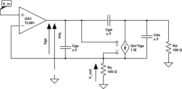
enter image description here

Someone says that is written on the datasheet, but also could not. In this latter case we should need the internal circuitry to estimate it. Is that true? If so, how can I find this value from, for example, an LM324? That impedance seems to be not present inside the datasheet.

EDIT: But I may be wrong, in that circuit I need to model the output of the op amp as a voltage generator+output resistance. I was thinking to open loop only because the oputput of the system in which the feedback takes the signal is not the output of the opamp. But if I'm wrong, I can find the output resistance with the normal closed loop way. Would still be right even if the feedback of my circuit is a drop due to a current and not the output voltage directly from the opamp? I think the answer would be 'yes' because the output is still dependent on the output of the opamp, of course.

\$\endgroup\$
6
  • \$\begingroup\$ Ok, based on your other comments to some answers, MOSFET driving appears to be the app... and additionally you're looking at the high-frequency behavior. (All this should have been spelled out in your question!) In this scenario, you should at least model the opamp using the Boyle macromodel, which has two resistors on its output (one gives the high-frequency output resistance, and their sum gives the DC resistance). But beware (see my comments to Spehro Pefhany's answer) that even that may not be detailed enough given how the LM124/LM324 is modelled by its creators... \$\endgroup\$ Commented Jan 4, 2015 at 18:55
  • \$\begingroup\$ Well, I didn't say that because it is not important what I'm driving. What is important is, with that given circuit, know how to estimate the output resistance if I look inside the op-amp. (that is a MOS simplified equiavalent circuit, but could be anything, it's a general purpose question). So, the question is what would do someone which is "expert"? Not asking for a job done, but for an advice, an indication to the right way. So you would use the Boyle macromodel to estimate how R out influence the circuit? \$\endgroup\$
    – thexeno
    Commented Jan 4, 2015 at 19:16
  • \$\begingroup\$ I would use the most advanced/elaborate (SPICE) model for the opamp that I can find. A single ohmic value (which seems to be what you're looking for) probably won't model it well enough, especially not from to DC to high-frequency. For some simple (fairly) low-frequency applications, which I first thought [in my now deleted answer] you might be inquiring about, a single ohmic value will do. But not for the high-frequency stuff you're asking about. Spehro Pefhany's answer is closer to the mark on that, but even he evaded actually extracting a single value from that macromodel... \$\endgroup\$ Commented Jan 4, 2015 at 19:26
  • \$\begingroup\$ For high-frequency analsys (among other things) the multipole zero (MPZ) model is superior to Boyle's... but you'll only find one for fairly new opamps. Actually, the LM124 SPICE model from Nat Semi (now TI) appears to be one of those given the output inductor it has. \$\endgroup\$ Commented Jan 4, 2015 at 19:31
  • \$\begingroup\$ And one more thing that I should mention (perhaps I should write an answer after all) is that "MPZ" is TI's name for this kind of model. The same general ideas, including output through an inductor is called the "ADSpice model" by AD. \$\endgroup\$ Commented Jan 5, 2015 at 0:36

3 Answers 3

2
\$\begingroup\$

Open-loop output impedance of a opamp is rarely, if ever specified. However, the maximum current source and sink capability usually is.

You should therefore go with the datasheet and consider the opamp output a current source within the maximum specified current capability. It's impedance should therefore be considered infinite, since that is the impedance of a perfect current source.

In reality, the impedance won't be infinite, but you don't know what it will be. CMOS output opamps probably look mostly resistive, but the current source model may actually be closer for bipolar output opamps.

In any case, don't try to read into the datasheet what it doesn't say. You are only guaranteed what it guarantees. Assume the current source model when designing the circuit, and everything should work. If you design the circuit right, the open-loop output impedance will be irrelevant anyway. In the closed loop case, the output impedance, like the gain, will be governed by the feedback.

\$\endgroup\$
3
  • \$\begingroup\$ Heh. This is a good example of why you should never entirely trust simulations. The model you incorporate into the simulatioin may or may not correspond to the real device, or at least not closely enough for your particular application. Simulations are excellent for some things, but models based on data sheets, with their unspecified qualities, are no substitute for a real device in a real circuit. \$\endgroup\$ Commented Jan 4, 2015 at 15:03
  • \$\begingroup\$ @olinlathrop I read links and stuff around, and from what I heard and read, what you say seems the best less-exoteric way to consider things. If I assume the curren source model, as you suggest, in what way "everything should work"? When driving cap loads, I always see the Ro value. I think I am missing something. \$\endgroup\$
    – thexeno
    Commented Jan 6, 2015 at 16:22
  • \$\begingroup\$ I've nearly forgot a precisation: the LM324 is not a sink like others, but have a normal common emitter configuration, so ideally should be zero (and not infinite). There is also the protection circuit which introduce a variation and so on.. And since I have an high closed loop feedback gain, that impedance I think could be even smaller. But Murphy's law apply. \$\endgroup\$
    – thexeno
    Commented Jan 6, 2015 at 20:39
2
\$\begingroup\$

As Olin says open loop output impedance (\$Z_o\$) is rarely specified. It's because it's not just a constant resistance,but usually a function of frequency and temperature, and also not really linear. As Spehro says, it's not much of a care about, except for stability or driving capacitance. But since it looks like you are trying to control a FET with a LM324, you will probably care about it a lot.

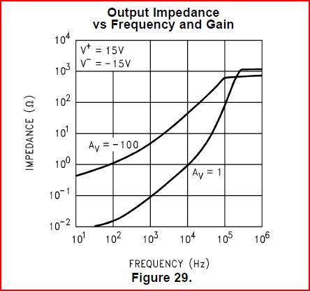
While \$Z_o\$ is rarely given, closed loop output impedance (\$Z_{\text{oCL}}\$) is much more common. With \$Z_{\text{oCL}}\$ and amplifier gain (\$A_v\$), \$Z_o\$ can be calculated. Usually a unity gain curve is given, and from the classic feedback equation of Black, \$Z_o\$ can be calculated as:

\$Z_o\$ = \$\left(A_v+1\right) Z_{\text{oCL}}\$

The LM324 is in the same family as the LM611, which does show a curve of \$Z_{\text{oCL}}\$. Now the output stage of the LM611 was improved over the LM324 to reduce crossover distortion, so \$Z_o\$ will be a little better but similar to the LM324.

LM611 output impedance

First, you can see that the output impedance of this family of OpAmps is high. Once outside the gain bandwidth of the OpAmp, \$Z_o\$ and \$Z_{\text{oCL}}\$ become equal. So, for LM324, LM611 \$Z_o\$ is ~ 1KOhm. But it isn't really resistive. In fact it's only resistive between about 300Hz and 10KHz. Between 10KHz and 300KHz \$Z_o\$ appears to become inductive (really there's just some non-linearity that makes it look inductive). It is possible to calculate \$Z_o\$ from this curve for \$Z_{\text{oCL}}\$.

A curve like that of \$Z_{\text{oCL}}\$ is usually the best information that you will get from a datasheet.

Also relevant here might be "Stability problem in unity gain OpAmp".

\$\endgroup\$
3
  • \$\begingroup\$ That probably explains why there's an output inductor in the LM124/LM324 SPICE model that TI gives out. \$\endgroup\$ Commented Jan 5, 2015 at 0:40
  • \$\begingroup\$ @Respawned - I've not looked at their model, but could be, and it looks like close to 1mH too. \$\endgroup\$
    – user16497
    Commented Jan 5, 2015 at 0:51
  • \$\begingroup\$ I've some concerns on model the Zo over a swing of frequency. Like plotting a bode plot on Matlab: I need a function approximation. I feel that as wrong, seems too insane to me. But as I can read on AD application note, maybe a bit of empirical design should be adopted. D'oh :) \$\endgroup\$
    – thexeno
    Commented Jan 6, 2015 at 16:24
1
\$\begingroup\$

The usual assumption is that it's less than 100 ohms for normal (not very low power) op-amps and often much worse for very low power op-amps. You may be able to find an estimate of the nominal value by reverse-engineering the SPICE model (although the below-linked article from AD indicates that the modelling of Ro may be quite inaccurate).

It's an important number (especially the upper limit of open-loop output resistance) if you anticipate substantial capacitive loading of the op-amp and wish to evaluate stability, but unfortunately it's not generally directly guaranteed. You typically will find some guarantee of stability (such as phase margin) with a given capacitive loading in the datasheet. From that, you could work backwards to a limit on the output resistance.

As Olin says, it's bad engineering to depend on parameters that are not directly or indirectly guaranteed on the datasheet, so it's best to isolate that capacitive loading or otherwise make the circuit relatively insensitive to output resistance so even if it turns out to be relatively high your circuit will still work to specifications.

Edit, re your edit:

The open-loop output resistance can affect the stability of the circuit, especially with capacitive loading, because it puts another pole in the feedback path. If this is a consideration, you need to have some idea of what that resistance is, even though it's not directly specified on the datasheet, so it's a good idea to have a rough idea of what the nominal and limits are, otherwise you're just guessing that it will be stable. In the case where a resistor and AC feedback is used to stabilize the circuit (called in-loop compensation), you still need to have some basis for picking the value of that resistor. Is 50\$\Omega\$ okay, or must it be 1000\$\Omega\$?

Aside from stability considerations, normally we don't need to think too much about the open-loop output resistance of the op-amp- it's effectively reduced by the gain, so it tends to be negligible if the amplifier gain is high in comparison to the required accuracy.

\$\endgroup\$
20
  • \$\begingroup\$ I made an EDIT, which seems to be more coherent with your suggestion to be not dependent on undeclared values. Check it out and let me say if it's right, if you want. \$\endgroup\$
    – thexeno
    Commented Jan 4, 2015 at 16:17
  • \$\begingroup\$ I have actually looked at the LM124 SPICE model (from Nat Semi now TI) and compared it with the Boyle macromodel (paper), which uses two resistors (one is the AC output impedance at high frequency, and their sum gives the DC output impedance) but I'm having trouble applying that scheme to the actual LM124 SPICE model, which has 3 resistors (and an inductor) in its output stage. Since you mentioned reversing the SPICE model (evil grin), it might be illustrative if you could work out the LM124 as an example. \$\endgroup\$ Commented Jan 4, 2015 at 18:35
  • 1
    \$\begingroup\$ Well, if you're looking for 0.1% accuracy at a gain of 1 you only need about an open-loop gain of 1000, so it sounds like you're fine as even the worst op-amps generally have minimum guaranteed gains in the tens of thousands. Things get a bit fussier with high-Q active filters- you might need to multiply by the Q of the filter. \$\endgroup\$ Commented Jan 4, 2015 at 19:47
  • 1
    \$\begingroup\$ The suggestion to look in the SPICE model works better for the more mundane NE5532/NE5534. TI gives only a bog standard Boyle macromodel with RO1 50 and RO2 25. So at DC the open-loop resistance is 75 ohm and at high frequency it is 50 ohm. \$\endgroup\$ Commented Jan 4, 2015 at 22:31
  • 1
    \$\begingroup\$ @RespawnedFluff Without any fancy reverse engineering, I simply connected an LM324 in PSPICE with offset applied so it was within 100mV or so of 0V (+/- 7.5V supplies) and nothing connected to the output. Applied a 2mA p-p 10Hz sine wave to the output and got 128.54mV swing at the output (about +18mV to -109mV), so output resistance is 64.3 ohms. Not unreasonable. \$\endgroup\$ Commented Jan 5, 2015 at 0:34

Your Answer

By clicking “Post Your Answer”, you agree to our terms of service and acknowledge you have read our privacy policy.

Not the answer you're looking for? Browse other questions tagged or ask your own question.