1
\$\begingroup\$

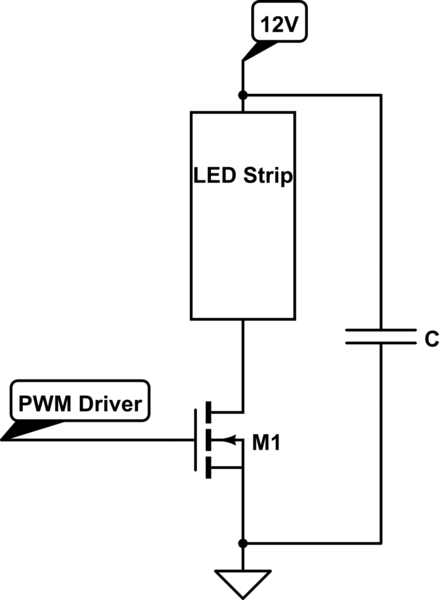
I have a number of LED strips (the simple versions: 3 LED + resistor per "section") that I want to modulate with a PWM driver at ~ 1kHz. The design looks like:

schematic

simulate this circuit – Schematic created using CircuitLab

My expectation is that the capacitance C is going to be related to the output impedance of the 12V power supply, however I'm not sure how to determine the output impedance of the power supply.

If I could narrow down the impedance at 1kHz of the power supply, I could use that for a low pass filter. However I'm not sure if there is a simpler way to figure out the correct bulk capacitance.

\$\endgroup\$
14
  • 1
    \$\begingroup\$ Have you determined that a capacitance is required at all? \$\endgroup\$ Commented Sep 23, 2016 at 4:59
  • 1
    \$\begingroup\$ @IgnacioVazquez-Abrams: I haven't. At the moment, I haven't chosen a power supply, so I can't tell if the capacitance is needed. I'm designing the PCB for it at the moment, and am trying to figure out if I should add room for the rather large caps I believe I will need. Another way of phrasing this might be "when is bulk capacitance needed?" \$\endgroup\$ Commented Sep 23, 2016 at 5:10
  • 1
    \$\begingroup\$ The length of the wires between the power supply and LED strip will make a big difference on how much C you need. \$\endgroup\$
    – Daniel
    Commented Sep 23, 2016 at 5:13
  • 1
    \$\begingroup\$ I have experienced this many times, debugging hardware, getting strange results, then cutting the supply wires down which makes the problem disappear. You have the inductance, and also the wire resistance is a problem when a partially bypassed device tries to take a large gulp of current, which can be 10s of amps. \$\endgroup\$
    – Daniel
    Commented Sep 23, 2016 at 6:39
  • 1
    \$\begingroup\$ @AndrewSpott Just put capacitance where you need it, and if you have a higher-impedance pinch point (like feed wires or a wire harness) make sure that you're locally bypassed. Sense wires probably will not improve this problem since it needs to respond very quickly. \$\endgroup\$
    – Daniel
    Commented Sep 23, 2016 at 16:20

1 Answer 1

2
\$\begingroup\$

VA rating on 12V supply must exceed stripled Watt rating. These are design for automotive 14.2 at max brightness. These are not highly efficiently with a threshold of around 9V and are rated in Watts per foot or per meter.

The problem with many wall wort supplies is the internal cap may not be rated for the pulsed ripple current you intend to apply and prefer to be run at constant load .

You can use a surplus PC PSU at 12V or perhaps a universal laptop charger which is less robust but may have a selection for 15V at 4A or more.

to choose a cap for unknown flakey supply, it must handle the RMS current you intend to switch. So if 5App 50% assume 2.5A and choose a cap rated >3A rms ripple current.

to choose c value at 1K or 10kHz compute C for 10 cycles using R=Watts/(I^2) as the load is quasi linear with series R's.

e.g at 1kHz and RC=10cyc/1kHz=10ms or 1ms @10kHz

  • thus if strip leds are 5A, for cap sag of 10%V in 1ms @10kHz,
  • Ic=Cdv/dt so C=5A*1ms/1.4V=3600uF rated at >=16V

3600uF/16V is not avail, but 2200uF is avail here. Ripple current =8.1Arms radial leaded $1.5 , get two

  • 1kHz would need 10x bigger cap. Mosfet should have RdsOn<<100mOhm@5A for no heatsink @0.5W dissipation, lower is better and can be driven by NE555 PWM clock.
\$\endgroup\$
11
  • \$\begingroup\$ Why do you choose the diodes as the R in the RC vs the output impedance of the power supply? \$\endgroup\$ Commented Sep 23, 2016 at 16:13
  • 1
    \$\begingroup\$ Good question, but I made no assumption on the Zout of the supply, only that VA rating exceeds W load for same 12V. It could be low Zout from a DC-DC or higher unregulated source, which doesn't matter since stripLEDs are designed with large (e.g. 68-82Ohm) series R's per series string, then replicated in parallel to accommodate 11 to 14.2V typical range with varying brightness. The series R in the stripLEDs will always be larger than Zout of compatible 12V supply and may fail with an early lifetime. (e.g. <1yr). Thus you were wise to ask about sizing a suitable cap., but not 1kHz. maybe (25k) \$\endgroup\$
    – D.A.S.
    Commented Sep 23, 2016 at 21:12
  • 1
    \$\begingroup\$ Unfortunately, 1kHz is the driver that I have available. At 1kHz I also don't have to worry about using a driver for my mosfets (the PWM chip can drive them at that frequency for a reasonable rise time) and I can mitigate the necessity of the external caps by shifting the different PWM phases around. \$\endgroup\$ Commented Sep 23, 2016 at 22:15
  • 1
    \$\begingroup\$ Could someone go over that answer and make it a little more readable for those of us who are not so well-versed in math and the lingo of electrical engineering? Things like "stripled" or "c value" I can edit myself. But what does the author mean by "cap sag" and "Cdv/dt" or "Arms"? As for the price of the suggested capacitor for OP's example, I'd remove that since prices are too much in flux these days... \$\endgroup\$
    – Sixtyfive
    Commented Apr 23, 2022 at 18:18
  • 1
    \$\begingroup\$ Ic = cap current = C [F] * dV [V] / dt [sec] ... standard cap equation Amps (rms) = Arms \$\endgroup\$
    – D.A.S.
    Commented Apr 23, 2022 at 21:33

Your Answer

By clicking “Post Your Answer”, you agree to our terms of service and acknowledge you have read our privacy policy.

Not the answer you're looking for? Browse other questions tagged or ask your own question.