2
\$\begingroup\$

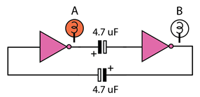
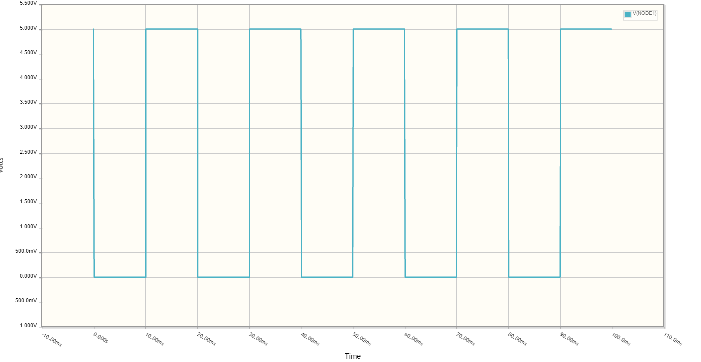
I built the following circuit and it oscillates at about 1 Hz. I can't figure out however how it works. I picked the design up from an old Bernard Babani book (1979) on 7400 series ICs. The book doesn't explain how it works either. The book uses a 7400 to supply the NOT gates (combining two NAND gate inputs to form a NOT gate). I don't do that, instead I have a transitor based circuit that behaves as a NOT gate. However it oscillates as the book suggested it would. I implemented the circuit in circuitlab and I can get the simulation to show square wave oscillations, see below.

enter image description here

Simulation from circuitlab

enter image description here

\$\endgroup\$
19
  • 4
    \$\begingroup\$ I havn't tried simulating it on CircuitLab yet - Try it then. \$\endgroup\$
    – Eugene Sh.
    Commented Jun 23, 2017 at 18:22
  • \$\begingroup\$ I will, but from your comment I presume you don't know how it works either? \$\endgroup\$
    – user84299
    Commented Jun 23, 2017 at 18:45
  • 2
    \$\begingroup\$ We encourage to exhaust the own research capabilities before asking a question. You haven't done with yours yet. \$\endgroup\$
    – Eugene Sh.
    Commented Jun 23, 2017 at 18:48
  • 2
    \$\begingroup\$ It won't oscillate for ideal components. Try redrawing the gates with some finite input impedance. \$\endgroup\$
    – Eugene Sh.
    Commented Jun 23, 2017 at 19:15
  • 2
    \$\begingroup\$ @ rody Using bipolars, with base resistors, this is the classic astable oscillator. See Figure 1 on this link en.wikipedia.org/wiki/Multivibrator \$\endgroup\$ Commented Jun 24, 2017 at 4:33

1 Answer 1

3
\$\begingroup\$

This circuit is a variant of so-called "astable multivibrator", see Wikipedia.

An astable multivibrator consists of two amplifying stages connected in a positive feedback loop by two capacitive-resistive coupling networks.The amplifying elements may be junction or field-effect transistors, vacuum tubes, operational amplifiers, or other types of amplifier.

Two inverters form a non-inverting amplifier, so the feedback loop is positive. Timing for flip-flops is determined by capacitors values times some input impedance (or current, for TTL).

CLARIFICATION: The TTL inverters have essentially DC floating inputs in this circuit. Initially, parasitic leakages move the input voltages up crossing the switching threshold area, so the gates essentially enter the linear amplifier regime. The rest happens similar to the ordinary BJT multivibrator, initial state is based on realistic differences in element parameters, and then the switch frequency is determined by discharges of caps into input impedance of the circuit.

\$\endgroup\$
6
  • \$\begingroup\$ Its more complex that you make out. It is true that two inverters in a cycle will have two stable states, 10 and 01. Its only the with the capacitors that makes the state unstable. I'm 90% certain that what we have then is a relaxation oscillator. Thankfully I found a much fuller explanation in an obscure article. \$\endgroup\$
    – user84299
    Commented Jun 24, 2017 at 21:00
  • \$\begingroup\$ @rhody, young man, which part of "...feedback loop by capacitive-resistive coupling network..." did you miss? \$\endgroup\$ Commented Jun 25, 2017 at 0:10
  • \$\begingroup\$ Capacitive-resistance coupling is a generic statement, it just sugegsts transfer of energy, doesn't explain what is going on in a specific case. I found an explanation in an article from the 60s. You might be unsure of the details of this circuit, you would have given it if you did. I am sure you know the big picture. The quote you give is a prelude to the transistor multivibrator (TM) which is not in detail how my circuit works. I understand the TM perfectly but the one I gave is more subtle. True there are capacitors and feedbacks but the details differ. This is WHY I posted the question. \$\endgroup\$
    – user84299
    Commented Jun 25, 2017 at 21:58
  • \$\begingroup\$ @AliChen 74xx series TTL has pull-ups on the inputs, not floating. \$\endgroup\$ Commented Jun 26, 2017 at 5:30
  • \$\begingroup\$ @Jasen, no, original TTL did NOT have any pull-ups, please check their actual schematics diagrams, e.g. allaboutcircuits.com/worksheets/ttl-logic-gates/#24 or go straight to Texas Instruments pages. Maybe some modern series do, I am not sure, but it does not change the basic idea. \$\endgroup\$ Commented Jun 26, 2017 at 14:28

Your Answer

By clicking “Post Your Answer”, you agree to our terms of service and acknowledge you have read our privacy policy.