6
\$\begingroup\$

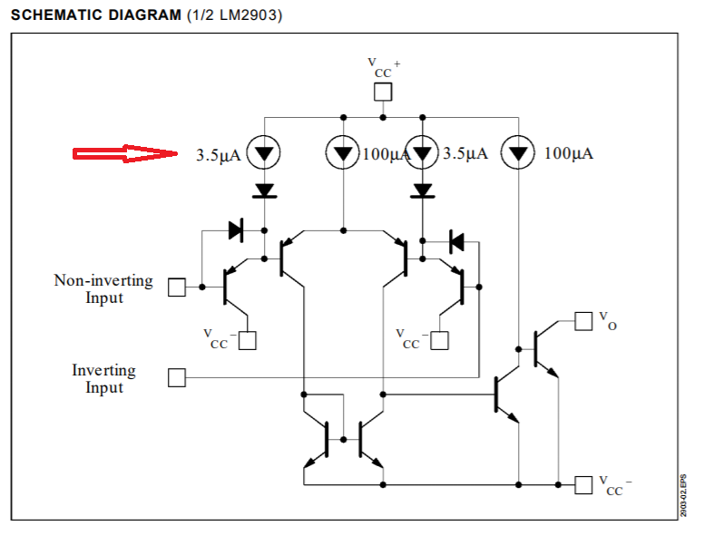
Below is a schematic diagram given for an IC in its datasheet:

enter image description here

As you can see everything is drawn in detail in transistor level. I can see many BJT transistors and diodes for instance.

But the 3.5uA and 100uA current sources are not drawn in transistor level. Why are the current sources hidden here and shown only as a current source symbol? Why are not they drawn explicitly?

\$\endgroup\$

3 Answers 3

17
\$\begingroup\$

Most likely just to simplify the schematic. They would likely be implemented with various scaled and interconnected current mirrors as well as some sort of reference current generation circuit. One complicating factor is that this is 1 channel out of 2 on the chip, and it's entirely possible that the biasing circuitry is shared between the two channels in various ways.

It's common for the biasing circuitry to be relatively complex as it has to provide lots of different currents to different parts of the circuit, and maintain accuracy despite voltage and temperature variations. However, the biasing circuitry simply ends up generating some well-controlled reference voltages and currents, so drawing those on the schematic as sources makes it much easier to read and understand the important functional parts of the circuit.

\$\endgroup\$
2
  • \$\begingroup\$ Any known cases where actual single-JFET current sources are used and implemented as one part? \$\endgroup\$ Commented Jan 2, 2018 at 15:03
  • 1
    \$\begingroup\$ @rackandboneman -- usually only for a "bootstrap" if a pinch resistor isn't suitable for the job, as JFET current sources are kinda sloppy... \$\endgroup\$ Commented Jan 2, 2018 at 15:24
4
\$\begingroup\$

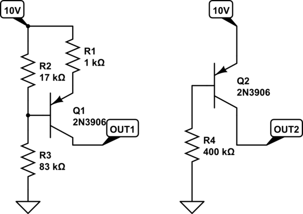
Drawing out a current source by showing the exact circuit used would often make things less clear, since the designs of practical current sources will often be sensitive to component variations. To understand way, look at a couple of simple ways a 1mA current source might be implemented on a chip which is specified only for operation at exactly 10.0 volts:
schematic

simulate this circuit – Schematic created using CircuitLab

The approach on the right may work if the transistor happens to have a voltage drop of exactly 0.7 and a beta of exactly 43.01, or if its voltage drop and beta have the proper relationship, but uncertainty in those parameters (especially beta) could yield to significant variations in current. The circuit on the left would have an output current that is more sensitive to voltage drop, but far less sensitive to beta.

As technologies change, chip designers may have more or less precise control over different aspects of transistor behavior, and might thus have reason to favor one approach over the other. Someone using the part, however, would have little reason to care about whether the designer used a transistor with a very precisely controlled beta, or used emitter resistance to reduce beta dependence, or used some other means to ensure predictable behavior. There's thus no reason to include such details in an end-user schematic.

\$\endgroup\$
1
\$\begingroup\$

It must also be understood that just because a chip's schematic has transistors, it doesn't mean you can buy similar transistors. The schematic is there to understand the function of the chip, but you won't obtain anywhere near similar function/performance, not even at DC, if you just copy the circuit in discrete parts. The critical transistors in the chips are often specially arranged and partitioned for thermal compensation, and for compensation of across-the-die parameter variation. The various approaches to this were perfected in the 70s and early 80s, and are in the bag of tricks of most analog IC designers.

If you'd want to implement the comparator schematic you've mentioned, in discrete components, you'd be best served by using discrete programmable current sources. They look like transistors and come in 3-terminal packages: LM334! This chip is still hard to beat for quick experiments. It's a respectable part, considering how simple it is.

In analog circuit design, current sources and current mirrors are building blocks no different from transistors: you can just buy them and use them, no need to design your own unless you need some special properties that off-the-shelf solutions don't provide. Those usually aren't simple to implement out of discretes on a breadboard either.

\$\endgroup\$

Your Answer

By clicking “Post Your Answer”, you agree to our terms of service and acknowledge you have read our privacy policy.

Not the answer you're looking for? Browse other questions tagged or ask your own question.