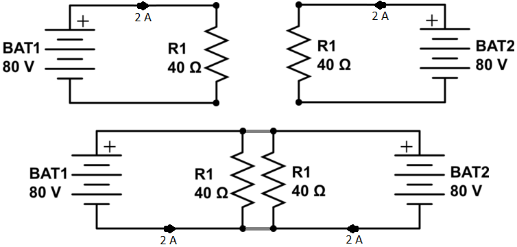
Here is how the superposition principle is being misapplied.
When we apply the superposition method, we consider each energy source in the circuit in isolation, while "turning off" the other energy sources. Then we add the results. "Turning off" the other energy sources means reducing them to zero: 0V for voltage sources and 0A for current sources.
Now, (ideal) voltage sources have an impedance of zero. So when they are turned off, they become a short: a piece of ideal wire. Ideal current sources have infinite impedance. When they are turned off and generate 0A current, they are open.
Thus, in a nutshell: voltage sources not being considered are shorted; current sources open.
The teacher's mistake is replacing the excluded power source, a voltage source, with an open circuit: literally yanking it out of the circuit diagram. That is only correct for current sources.
However, when we do the analysis correctly, we instantly run into the problem that the battery we are analyzing is being short-circuited by the one we set to 0V which calls for the flow of infinite current. So what can we do is model the resistance of the wires with some negligible values, like 0.001 \$\Omega\$ so that we are then dealing with a finite (but large) current through those parts of the circuit.
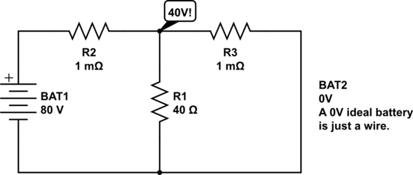
simulate this circuit – Schematic created using CircuitLab
Aha! And so now what happens is that most of the current action is flowing through the R2-R3 voltage divider. The circuit node between R2 and R3 is sitting at almost exactly 40V, and so R1 sees 1A of current.
Of course, the intermediate voltage is very sensitive to the values of R2 and R3 being exactly equal, which isn't realistic. This is not a problem.
Suppose that R2 and R3 are instead 1 and 3 \$\text{m}\Omega\$. Then we have a 1:3 divider, so the voltage at the given node is 60V. But in that case, when we analyze with opposite battery, the divider is reversed and we will get 20V. So we get 0.75A from one analysis and 0.25A from the other: they still superimpose to 1A through R1.
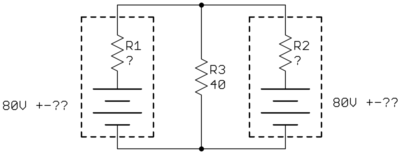
(To model this with greater realism, we have to include internal battery resistance. That is to say, we do not replace the batteries that we are not analyzing with short circuits, but with their internal resistance.)
Why the simplified voltage-divider reasoning applies: it is because the small R2-R3 values swamp the big R1 value. We can draw the analysis circuit like this:
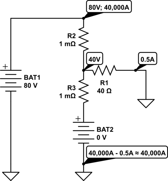
simulate this circuit
When the impedance through a voltage divider is less than around twenty times smaller than its load (1:20 rule), we can pretend that the load is not there when calculating the midpoint voltage. Here the difference is many thousands, by deliberate choice of R2 and R3.
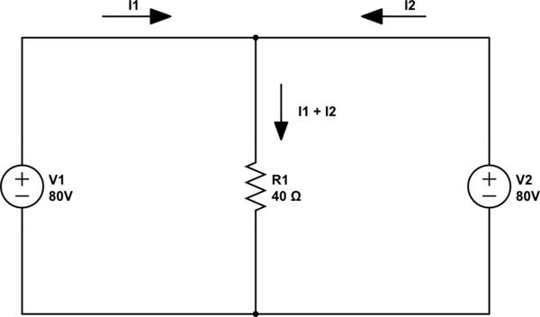
Of course, instead of this short-cut reasoning, we can do the exact analysis whereby the current through R2 is equal to the sum of the currents through R3 and R1, and the midpoint voltage ends up being slightly less than 40V due to the tiny loading effect of R1.


