0
\$\begingroup\$

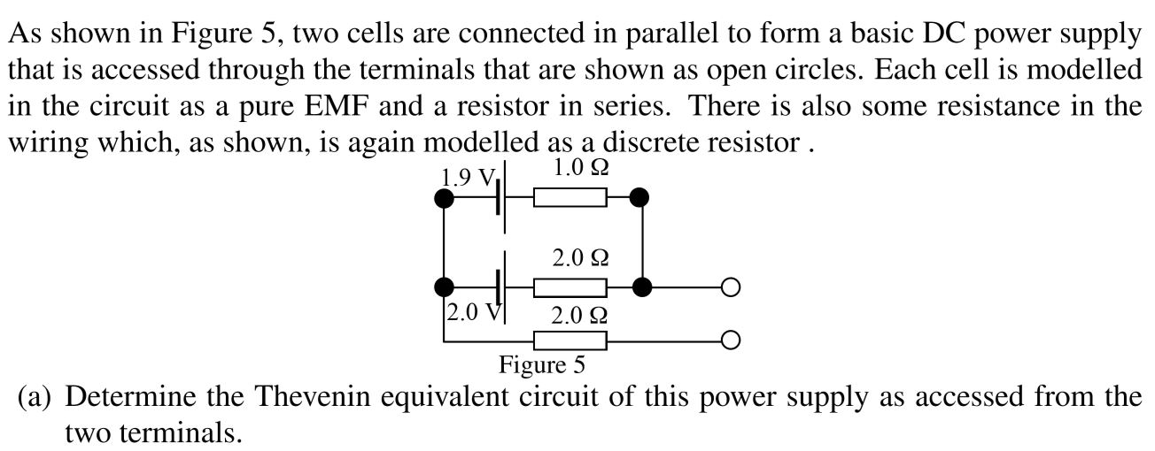
I am tasked with the following exercise:

enter image description here

I am still finding Thevenin equivalent circuits challenging, and this example looks a bit daunting since it seems to have an external loop.

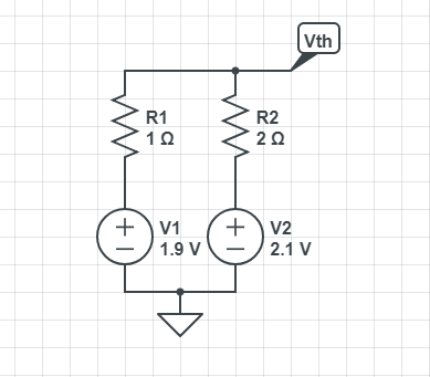
Hopefully, I made the correct assumption (though I could very much be wrong) that I only needed to find the equivalent circuit of the OPEN LOOP of this circuit. Namely, creating a thevenin equivalent circuit of this:
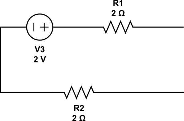
schematic

simulate this circuit – Schematic created using CircuitLab

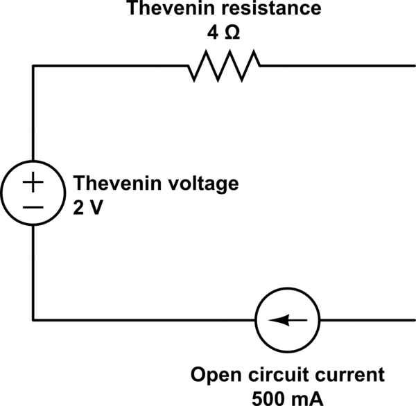
Which led me to getting the following Thevenin Equivalent circuit:
schematic

simulate this circuit

Was my assumption correct? If not, how do I account for this? For example, this external circuit would make finding the open circuit voltage no different, I would think.

\$\endgroup\$
2
  • \$\begingroup\$ The second supply is not an "external loop", it is very much part of the circuit to which you have to find the thevenin equivalent. You could use superposition principle here and deal with one supply at a time, if you so desire. Side note: "open circuit current" is always 0. \$\endgroup\$ Commented Apr 21, 2018 at 19:57
  • \$\begingroup\$ Your last circuit is nonsense: in an open circuit there cannot be any current, so that current generator is an absurd (if it were possible, it would induce an infinite voltage across the open terminals). The Thevenin (DC) equivalent circuit is simply a voltage generator in series with a resistance. \$\endgroup\$ Commented Apr 21, 2018 at 19:57

2 Answers 2

1
\$\begingroup\$

To find Vth

Currents flow only in close loops. You opened two terminals in the circuit. It means, no current will flow through the lower 2 ohm resistor. So you can discard it. Draw the circuit in an understandable manner then.

enter image description here

You can any method like KVL, nodal voltage, superposition theorem etc to find Vth.

Use KVL, assuming I is the current in the circuit: $$V_1 - IR_1 - IR_2 - V_2 = 0$$

On solving \$I = -66.66 mA\$

Therefore - $$V_{th} = 2.1 + IR_2 \approx 2 V$$

To find Rth

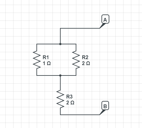
Go back to the original ckt. Short all voltage sources. Open all current sources. The result is:

enter image description here

Rth = R3 + R1||R2 = 8/3 ohms.

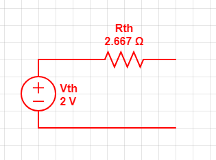
Hence the thevenin eq. ckt -

enter image description here

There is no "open circuit current" source as you drew in the ckt.

\$\endgroup\$
5
  • \$\begingroup\$ Thanks for this. When you found the Thevenin voltage, why did you find it with 2.1 + IR_2? How did you know to take that route to find the open circuit voltage? \$\endgroup\$
    – sangstar
    Commented Apr 21, 2018 at 23:51
  • \$\begingroup\$ You can choose any path. I chose the path through R2. You can choose R1 path too. You will get same answer. \$\endgroup\$ Commented Apr 22, 2018 at 13:59
  • \$\begingroup\$ Move from ground to the node at which you want to calculate the voltage. You can take any relevant path which reach you there. \$\endgroup\$ Commented Apr 22, 2018 at 14:01
  • \$\begingroup\$ But how do I know where ground is for this circuit? \$\endgroup\$
    – sangstar
    Commented Apr 23, 2018 at 20:51
  • \$\begingroup\$ Ground is whatever node you choose as reference to define voltage of all Other nodes in ckt. Here it is the negative terminal of battery. We used that point as the reference through out our analysis. \$\endgroup\$ Commented Apr 24, 2018 at 12:05
0
\$\begingroup\$

Some hints to find the Thevenin equivalent circuit.

  1. You must deactivate any independent source in your circuit (bring the generated quantity to 0). This means your two batteries become short circuits, i.e. piece of ideal wire.

  2. The circuit is now made up only of resistors. The equivalent resistance is the Thevenin equivalent resistance.

  3. In the original circuit determine the voltage at the terminals. That is the value of the Thevenin equivalent source.

For this last point, note that with nothing connected to the terminals, there is no current through the lower 2Ω resistor, hence there is no voltage drop across it. This means that the open circuit voltage is just the voltage across the upper terminal and the common node of the two batteries.

\$\endgroup\$

Your Answer

By clicking “Post Your Answer”, you agree to our terms of service and acknowledge you have read our privacy policy.

Not the answer you're looking for? Browse other questions tagged or ask your own question.