It's not that simple.
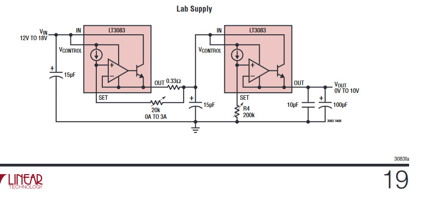
First off you do not put the entire thermal load on a linear regulator. You want to reduce PD with a serial power resistor on the supply line. Notice the 0.33Ω resistor on the output of the first LT3033. See page 16 of the datasheet to calculate its value.
to make this example work with the TO-220 package (3C/W junction-case
thermal resistance).
The 3°C/W package thermal impedance is used to compare general thermal performance between packages. This characteristic is often abused and misused in heatsink design.
θJC represents the lowest thermal impedance path from the junction of the IC to the outside world. In some cases it is to the top of the package. More often from the junction to the thermal pad.
When the need requires transferring a large heat load the T-220 package is not correct package even though it has the lowest θJC.
Surface mount packages provide the necessary heat sinking by
using the heat spreading capabilities of the PC board, copper
traces, and planes. Surface mount heat sinks, plated through-holes and
solder-filled vias can also spread the heat generated by power
devices
- LT3033 datasheet.
The thermal impedance needed for junction to ambient includes the entire thermal path including the solder, thermal vias, copper thickness (internal and external), and copper area. See tables 3-5 for examples of θJA
You cannot just look at the convection characteristics of a heatsink and pick one with the required corresponding heat transfer characteristics.
Heat sink selection must include the thermal resistance from the junction to the attachment point of the heat sink to be effective.
You cannot look at the system thermal dynamics, you must also understand the thermal heat transfer in between system input and output.
The main purpose of a copper plane is to spread the heat transferring the heat from the junction to ambient as quickly as possible. To use convection heat transfer which is the cross sectional area of the copper thickness and width.
A good source for PCB thermal design is Texas Instruments Application Note 2020 Thermal Design By Insight, Not Hindsight
It is generally recommended to use passive cooling to minimize field failures. A fan can be added to increase thermal performance of the device being cooled. For example I will use a passive heatsink that will prevent LEDs from burning up then add forced convection to improve the temperature sensitive radiant flux.
Heatsink selection is beyond the scope of this site. It is certainly much more complex than the amount of surface area or a single heatsink datasheet characteristic.
For example in natural convection the principles of velocity boundary layer development on vertical plates in air is an entire physics discipline. The distance between fins is very important, e.g.: C.W. Leung, S.D. Probert, M.J. Shilston, Heat exchanger: optimal separation for vertical rectangular fins protruding from a vertical rectangular base, Appl. Energy 19 (1985) 77−85.
I would recommend HeatSinkCalculator.com for help in choosing a heat sink. They offer a limited free account.
An inexpensive source of extruded heat sinks is heatsinkusa.com. Consider using the width of the heat sink as the length and get the least expensive one inch length. For example I will buy a one inch length their 12" wide heat sink for a 12" long strip of LEDs.

