1
\$\begingroup\$

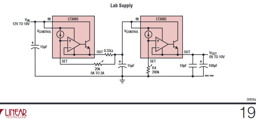
I was looking through a datasheet for the LT3083 regulator and in the typical applications sections this caught my eye: enter image description here

Provided input/output ratings could easily lead to over 20W being dissipated on the second regulator. I'm looking for some ballpark figures on the required heatsinking (i.e. size of the heatsink or perhaps active cooling requirements) to make this example work with the TO-220 package (3C/W junction-case thermal resistance).

\$\endgroup\$
0

3 Answers 3

1
\$\begingroup\$

If you output 2A @ 5v with a 15v input, there's your 20W approximately. So no argument there.

If you can keep the case exactly at ambient (22c), then you're looking at an junction temperature of 82c. The max specified is 125c, although I will say that I would not want to run it exactly at that point.

Now lets set the max ambient temp where the device will not malfunction as 32c (~90f). So now we're at a minimum junction temp of 92c, leaving 33c of headroom. This means your heatsink will need to dissipate 20W at 33c above ambient, giving a maximum coefficient of 1.65C/W (33C/20W).

Now lets look at some heatsinks and see if we can get that.

A large pcb mount passive heatsink (2.5in x 1in x 1.65in) won't do it (2.6C/W): https://www.digikey.com/product-detail/en/aavid-thermal-division-of-boyd-corporation/530002B02500G/HS380-ND/1216384

A little bit of airflow dramatically increases the efficiency. So if you look at heatsinks that come with an under-forced-airflow rating. You'll find many reasonable sized ones that can do it, for example this one: https://www.digikey.com/product-detail/en/ohmite/RA-T2X-25E/RA-T2X-25E-ND/2416487 It's only 1in x 1in x 1.65in, and with forced air it has a temp coeficient of 1.5 degC/W

To do this with natural convection only, you'll need a huge heatsink like this one. In case the link breaks, it 5in x 5in x 1.5in: https://www.digikey.com/product-detail/en/wakefield-vette/394-2AB/345-1176-ND/4864910

And remember, these are only barely enough.

\$\endgroup\$
1
  • \$\begingroup\$ That's pretty much where I got with my research, though I was pretty sure I'd missed something since I took the circuit right from the datasheet. I guess throwing some sort of switching regulator in the mix ought to help. Thanks for the answer. \$\endgroup\$
    – fardragon
    Commented Jun 29, 2018 at 18:52
0
\$\begingroup\$

Actually second regulator could be dissipating close to 50W if the input voltage is 18V, output current is 3A and output voltage is close to zero. Maximum junction temperature is 125C. So with a junction to case thermal resistance of 3 C/W you would be exceeding the junction temperature even with an infinite heat sink. For this to work at all the input voltage would have to be limited or the current limit reduced.

\$\endgroup\$
3
  • \$\begingroup\$ I wasn't thinking of going that low with output voltage, but with 16V input and let's say 3.3V/2A output it still get's pretty toasty with ~23W of heat. Would strapping it to a cpu cooler be enoguh? Although I'm starting to think that some sort of switching preregulator is the way to go here. \$\endgroup\$
    – fardragon
    Commented Jun 29, 2018 at 18:33
  • \$\begingroup\$ It's pretty cheap to buy these even with LED digits on Amazon \$\endgroup\$
    – D.A.S.
    Commented Jun 29, 2018 at 18:38
  • \$\begingroup\$ Yes a CPU cooler should be sufficient. \$\endgroup\$
    – Drew
    Commented Jun 29, 2018 at 18:52
0
\$\begingroup\$

It's not that simple.

First off you do not put the entire thermal load on a linear regulator. You want to reduce PD with a serial power resistor on the supply line. Notice the 0.33Ω resistor on the output of the first LT3033. See page 16 of the datasheet to calculate its value.

to make this example work with the TO-220 package (3C/W junction-case thermal resistance).

The 3°C/W package thermal impedance is used to compare general thermal performance between packages. This characteristic is often abused and misused in heatsink design.

θJC represents the lowest thermal impedance path from the junction of the IC to the outside world. In some cases it is to the top of the package. More often from the junction to the thermal pad.

When the need requires transferring a large heat load the T-220 package is not correct package even though it has the lowest θJC.

Surface mount packages provide the necessary heat sinking by using the heat spreading capabilities of the PC board, copper traces, and planes. Surface mount heat sinks, plated through-holes and solder-filled vias can also spread the heat generated by power devices
- LT3033 datasheet.

The thermal impedance needed for junction to ambient includes the entire thermal path including the solder, thermal vias, copper thickness (internal and external), and copper area. See tables 3-5 for examples of θJA

You cannot just look at the convection characteristics of a heatsink and pick one with the required corresponding heat transfer characteristics.

Heat sink selection must include the thermal resistance from the junction to the attachment point of the heat sink to be effective.

You cannot look at the system thermal dynamics, you must also understand the thermal heat transfer in between system input and output.

The main purpose of a copper plane is to spread the heat transferring the heat from the junction to ambient as quickly as possible. To use convection heat transfer which is the cross sectional area of the copper thickness and width.

A good source for PCB thermal design is Texas Instruments Application Note 2020 Thermal Design By Insight, Not Hindsight

It is generally recommended to use passive cooling to minimize field failures. A fan can be added to increase thermal performance of the device being cooled. For example I will use a passive heatsink that will prevent LEDs from burning up then add forced convection to improve the temperature sensitive radiant flux.

Heatsink selection is beyond the scope of this site. It is certainly much more complex than the amount of surface area or a single heatsink datasheet characteristic.

For example in natural convection the principles of velocity boundary layer development on vertical plates in air is an entire physics discipline. The distance between fins is very important, e.g.: C.W. Leung, S.D. Probert, M.J. Shilston, Heat exchanger: optimal separation for vertical rectangular fins protruding from a vertical rectangular base, Appl. Energy 19 (1985) 77−85.

I would recommend HeatSinkCalculator.com for help in choosing a heat sink. They offer a limited free account.

An inexpensive source of extruded heat sinks is heatsinkusa.com. Consider using the width of the heat sink as the length and get the least expensive one inch length. For example I will buy a one inch length their 12" wide heat sink for a 12" long strip of LEDs.
\$\endgroup\$
9
  • \$\begingroup\$ air heat transfer ~14W / 'Cm² is equal to about 56'C rise per sq.in per Watt (double sided) so 1sqin/W of heat sink area. to permit conductor rise of 56'C for sink exposed to free air, which may be rough, pipes or other shapes to improve surface area density which would apply to the equivalent rough surface area of a heat sink or the planar Alum surface of smooth alum. PCB is only effectively 1 sided as Epoxy is an insulator unless very thin and many thermal vias. so 2 sqin/W for PCB copper is my rule of thumb but depends on max ambient. \$\endgroup\$
    – D.A.S.
    Commented Jul 1, 2018 at 1:41
  • \$\begingroup\$ @TonyStewartolderthandirt I fail to see where your comment has any relevance to the topic even if it were correct. The point is there is not 20-30 watts that needs to be dissipated when a series power resistor is used to alleviate the thermal stress from the regulator. FR4 is a good conductor of heat when compared to air. The emissivity of the surface has nothing to do with convection as radiation which is hardly relevant here. Whether the surface is bare copper or solder mask has an insignificant effect on convection. Obviously you did not read the TI App Note Thermal Design By Insight... \$\endgroup\$ Commented Jul 1, 2018 at 1:57
  • \$\begingroup\$ You are not reading me as I intended. I did not confuse emissivity with convection, merely stated with free air condition vs (confined or force air) and 45 Watts could be dissipated with 18V input and output at 3V @3A so 15V*3A =? Why do you cover up your errors? \$\endgroup\$
    – D.A.S.
    Commented Jul 1, 2018 at 2:26
  • \$\begingroup\$ By conflating your ideas with what is presented you misinterpret your thoughts into criticsm rather than what is presented an adjustable CC followed by an adjustable CV with no heat loss R in series. Your insinuations are rude and offensive to my level of experience. when combined with errors in assumptions. I think we both agree the design has shortcomings if you do not realize the thermal heatsink required. But retrofitting a series R for a fixed low V high A is certainly correct. \$\endgroup\$
    – D.A.S.
    Commented Jul 1, 2018 at 2:58
  • \$\begingroup\$ I was designing LDO's in 1974 . How small of you. I guess you never saw the 5 Ohm resistor in my Falstad simulation before your answer \$\endgroup\$
    – D.A.S.
    Commented Jul 1, 2018 at 3:49

Your Answer

By clicking “Post Your Answer”, you agree to our terms of service and acknowledge you have read our privacy policy.

Not the answer you're looking for? Browse other questions tagged or ask your own question.