1
\$\begingroup\$

Oscillation on an 4 phase 12 to 24V 20A boost inverter

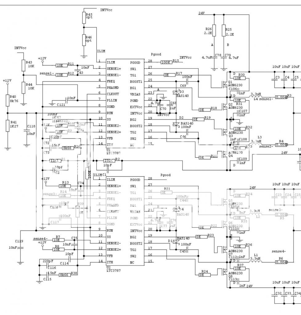
I’m using 2 pieces of LTC3787 to make a 12-24V inverter. I made a 4 layer board from it to have enough ground to make sure all will be stabile. But I have big oscillation on my output. With no load it’s ok. But with a few mA of load the trouble starts. I try to adjust the ITH RC values and tried only the master and the slave unit apart and tried connect my ground on different locations, canceled the 10pf caps on the voltage divider . So fare nothing worked out.

Hope some one can help me in were to look for to solve this issue schematic:
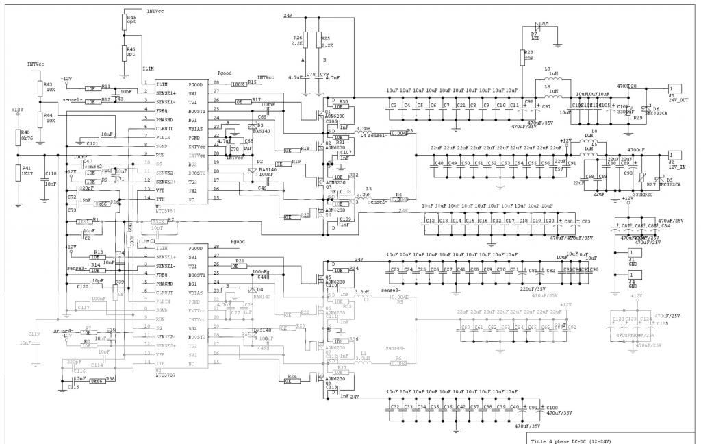
schematic [1]

main part schematic [1]

VGS low side FET

VGS low side FET [2]

VGS low side FET voltage

Input current - output ocsilation with 60mA load [3]

Input current - output ocsilation with 60mA load

yellow = current is 100mV/1A so top is about 75A spikes on the 12V input with 60mA load on the 24V side. blue is the output voltage rimple

ITH signal - input current [4]

ITH signal voltage - input current on the board 100mv/1A (about 75A)

Input current - VGS lowside FET [5]

input current yellow 100mV/1A- vgs lowside FET voltage

already thanks for all the help!!

\$\endgroup\$
5
  • \$\begingroup\$ Can you be more specific about the output oscillation - I've looked at the tek pictures and I'm not really sure what they are portraying (plus I'm lazy) \$\endgroup\$
    – Andy aka
    Commented Aug 30, 2014 at 16:31
  • \$\begingroup\$ if i add load on the output i get a about 50hz triangle rimple on my output with 1A load this is about top to top 6V also the input piek current is going to a few 100A with a load of just a few A on the output indeed forgot to add info with the pictures \$\endgroup\$
    – niels1
    Commented Aug 30, 2014 at 16:41
  • \$\begingroup\$ Are you sure your inductors aren't saturating? Have you run a bode plot with a network analyzer? Have you looked at the transient response for small load steps? Does it ring? Have you looked at Vin right at the input to the supply to see if it's stable? \$\endgroup\$
    – John D
    Commented Aug 30, 2014 at 19:18
  • \$\begingroup\$ Have you checked to see what the input voltage looks like - I think you might also see some large excursions of ripple at 18.2 Hz. Also, the Isense resistor, what value is it? \$\endgroup\$
    – Andy aka
    Commented Aug 30, 2014 at 19:46
  • \$\begingroup\$ i use PULSE PA1494.362NL coils they can do 17A and sat is around 20A. this coil was adviced in the datasheet by linear. i do not have a network analyser. Vin is from a good lab power supply. it has dips with the current spikes but is full stable outside of this. Isense risistor is 0,004 Ohm yes there is a rimple on the input as well with same frequency as the current spikes. the large i make the output current the worse it gets \$\endgroup\$
    – niels1
    Commented Aug 31, 2014 at 0:51

1 Answer 1

2
\$\begingroup\$

After reviewing the datasheet, it looks a lot like your system is going into burst mode at low loads, as shown at the bottom of page 5, and described on page 12. It may even be "locked into" burst mode for some reason.

However, it isn't at all clear why this is happening, since you seem to have all of the mode pins configured correctly. But this is the area I would focus on.

Just as a side note, your question is really way too long, with a lot of information that may or may not be relevant. It would be really helpful if you would eliminate all of the PCB layout diagrams (until asked for them) and focus on giving us a clearer description of what the scope waveforms represent.

\$\endgroup\$
0

Your Answer

By clicking “Post Your Answer”, you agree to our terms of service and acknowledge you have read our privacy policy.

Not the answer you're looking for? Browse other questions tagged or ask your own question.