I have a doubt about the meaning of input and output impedance of RF amplifiers. I'll take as example the amplifier CMA-252LN by Mini Circuits .
In its datasheet it is not clearly written their input and output impedances' values, but I think they are equal to 50Ohm since this is specified under the main properties of the amplifier, as you can see:
Now my question is: how are input and output impedances evaluated and what do they represent for this kind of amplifier?
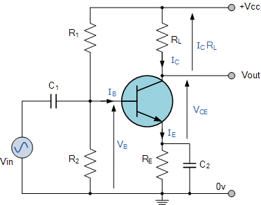
For instance, I have always evaluated both of them by using Thevenin theorem. For instance, with respect to the following BJT common emitter amplifier we evaluate its input impedance by short circuiting the power supply and by evaluating the ratio between input voltage and input current (while the output port is open), while we evaluate the output impedance by short circuiting the power supply and the input signal generator, and by putting a voltage source at the output port and by evaluating the ratio between output voltage and output current.
So, for istance for evaluating the output impedance, the input voltage Vin is shorted (so the input port is shorted). Is this the same procedure through which the output impedance of an RF amplifier is evaluated? Or is its input port closed on a 50Ohm load?


