1
\$\begingroup\$

Consider this active-RC circuit:
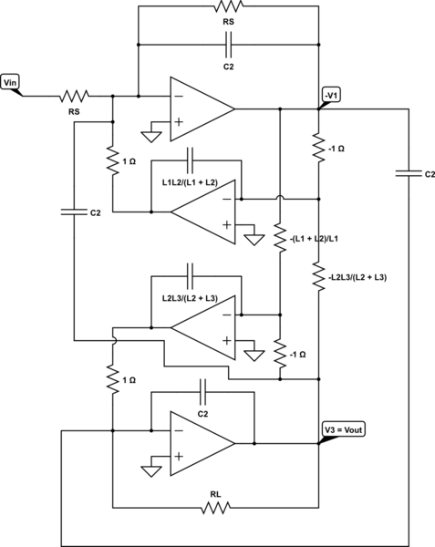
schematic

simulate this circuit – Schematic created using CircuitLab

it should exactly realize the RLC high-pass filter with one zero:

schematic

simulate this circuit

It realizes the same equations and so the same transfer function. This model has been used to obtain an analog, elliptic, high-pass filter with a low (about 0.01 Hz) cutoff frequency.

After a simulation (with negative resistor values, supposing that they are realizable), the active-RC transfer function seems to be the same as the RLC-prototype, but with a difference: a new and unexpected pole at a very high frequency, about 10 GHz.

After \$ f = 10 \ \mathrm{GHz} \$, the transfer function decreases regularly at 20 dB/decade and it is no more flat as it should be.

The opamps were realized through ideal VCVS generators (Voltage-Controlled Voltage Source), with a high gain (\$ 10^9 \$ at least).

If the order of the filter is increased, the pole decreases is frequency. For an eight-order circuit, it is at about 100 Hz!! And it is intolerable.

The RLC-prototype used for the 8th order circuit is

schematic

simulate this circuit

And it does not have any 100 Hz pole, despite of its active-RC realization (I don't draw it for shortness).

The simulator used is Spectre (from Cadence) and the values for the RLC prototype are taken from "A. B. Williams and F. J. Taylor, Electronic filter design, 3rd edition, McGraw-Hill, 1995" (both for the 3rd and 8th order filters).

So, are there in the topology of the active-RC some elements that could be generate such a pole? Or are there some undesired parasitics automatically inserted by that simulator?

Google didn't show anything useful.

\$\endgroup\$
19
  • \$\begingroup\$ The continuous decrease of the function (rather than being flat) is caused, of course, by the real opamp models with an open-loop gain that goes down with rising frequencies. \$\endgroup\$
    – LvW
    Commented Feb 6, 2015 at 13:02
  • \$\begingroup\$ No, the opamp have been modeled with ideal vcvs generators, with a gain of \$ 10^9 \$. \$\endgroup\$
    – BowPark
    Commented Feb 6, 2015 at 13:37
  • 1
    \$\begingroup\$ Check the default setting on your simulator. It may naturally add parasitic capacitance on each node. Micro cap does this and a few fempto farads at ten gig is not ignorable \$\endgroup\$
    – Andy aka
    Commented Feb 6, 2015 at 14:19
  • \$\begingroup\$ V3out is the output node of an IDEAL opamp (infinite gain, and zero r,out). Hence, this output must go down to zero for very large frequencies. \$\endgroup\$
    – LvW
    Commented Feb 6, 2015 at 14:26
  • 1
    \$\begingroup\$ @BowPark, I recommend to check if a change of the ideal opamp gain alters the unwanted pole. This would help to identify the source of your problem. \$\endgroup\$
    – LvW
    Commented Feb 11, 2015 at 13:08

1 Answer 1

1
\$\begingroup\$

Why would you worry about such a thing? It's a LF circuit. It won't do anything substantial at 10GHz - at least not anything you have any control over. It's all determined by the parasitics there. It's a case of a garbage result - simply ignore the response past 100MHz or so, depending on the speed of op-amps you're using.

\$\endgroup\$
4
  • \$\begingroup\$ I don't think it is determined by parasitic capacitances, which should not even be present in that fully-ideal active-RC circuit. I updated my question: raising the order of the circuit, the pole decreases its frequency and it is at about 100 Hz for an 8-order high-pass filter realized with the same procedure. Do you notice anything in the topology that could originate the pole? \$\endgroup\$
    – BowPark
    Commented Feb 9, 2015 at 10:58
  • \$\begingroup\$ @BowPark What I meant was that in a real circuit, the parasitics would determine the response, not whatever the simulator told you, or whatever you put into the circuit. At those frequencies, the shape of the traces is very, very important :) You need to try tell us exactly what 8 pole circuit did you simulate (I see none), and exactly in what software. I'd try it first in something other than CircuitLab first. For all I know, the values you use in your 8 pole circuit are bad. Where did you get the values? \$\endgroup\$ Commented Feb 9, 2015 at 16:05
  • \$\begingroup\$ Please, read the end of the question: I have updated it with some more informations. The values are correct, in fact the RLC prototypes have a high-pass behaviour, without any 10 GHz pole, both in the 3rd order and in the 8th order case. The 8th order circuit is built with the same procedure; it has simply the L1, L2, L3, C2 cell repeated 3 times and then a capacitor C8 before the load. \$\endgroup\$
    – BowPark
    Commented Feb 11, 2015 at 12:21
  • \$\begingroup\$ @BowPark Do you really expect us to have to look somewhere for the values you used for your filter and for the actual circuit that you've used? As it is, we can't even simulate it in CircuitLab. It's really on you to try to simulate it in multiple simulators and compare the behavior. You should only ask such a question when you verify that multiple simulators all agree on the behavior. \$\endgroup\$ Commented Feb 11, 2015 at 22:14

Your Answer

By clicking “Post Your Answer”, you agree to our terms of service and acknowledge you have read our privacy policy.

Not the answer you're looking for? Browse other questions tagged or ask your own question.