1
\$\begingroup\$

I am currently learning about transmission lines form an online book hosted by a website called “All About Circuits”. If anyone is interested, the particular chapter I am currently reading can be found here: http://www.allaboutcircuits.com/vol_2/chpt_14/6.html.

Basically, the book talks about having a circuit with a transmission line that looks like this:

enter image description here

The transmission line is supposed to be long enough so that:

  • At 250 kHz, the line's length is precisely right for 1/4 wavelength.
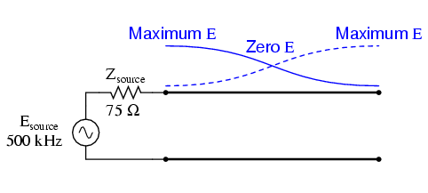
  • At 500 kHz, the line's length is precisely right for 1/2 wavelength.
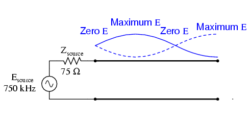
  • At 750 kHz, the line's length is precisely right for 3/4 wavelength.
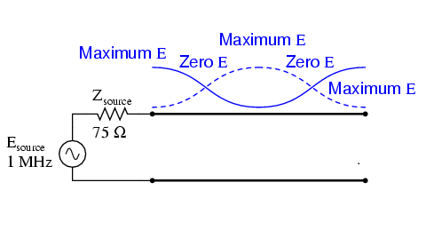
  • At 1000 kHz, the line's length is precisely right for 1 wavelength.

The images below show that standing wave graphically depicted with the frequencies mentioned above.

At 250 kHz, 1/4 wavelength:
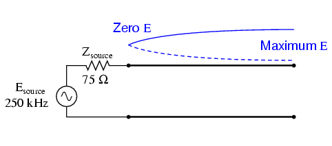
enter image description here

At 500 kHz, 1/2 wavelength:

enter image description here

At 750 kHz, 3/4 wavelength:

enter image description here

At 1000 kHz, 1 wavelength:

enter image description here

If you look at the standing wave for the mentioned frequencies, you will notice that the load end of the transmission line always has a standing wave antinode. I can understand this because the line is open so in my mind this makes sense.

What I don’t understand is why (depending on the frequency), we sometimes get a node and sometime an antinode on the source side of the transmission line. I don’t understand this because both the source and load sides are supposed to be endpoints which should mean that they should always be nodes or always be antinodes but not vary (at least that is my understanding).

Nevertheless, I am obviously missing something here so I was hoping someone could help me out and clarify what is going on here.

Thank you.

\$\endgroup\$

3 Answers 3

1
\$\begingroup\$

The devil's in the details, even if they are printed.

The trick is in the fact that the transmission-line is of characteristic 75 Ohm, and the excitation side is also 75 Ohm. Were that end very low source impedance it would tend much more to wanting a node (and as such forcing the need for an adjusted frequency = half the allowable frequencies), were it a very high impedance it would tend more to wanting an anti-node and again half the allowable frequencies.

The fact it is the exact characteristic makes that end reflection-less and in effect not a defining factor in the orientation of the standing wave. As such the open end gets to "dictate" the orientation on its own and the number of allowable frequencies for standing waves on the same line gets doubled.

\$\endgroup\$
1
\$\begingroup\$

Adding to what Asmyldof said, at 500KHz, & 1MHz, the reflected wave is in phase with the transmitter, taking the load off the transmitter. The line is acting like a parallel resonant circuit (& can be used as a resonant circuit). If the line was lossless, and was suddenly disconnected, the wave would keep reflecting back & forward forever.

At 250KHz & 750KHz, the reflected wave voltage is opposite phase, effectively putting a short circuit on the 75 ohm resistor, but this is a current point, so, to the line, it is just another node. The current flowing in & out of the resistor is the same as if there was an antinode behind it instead. If you were to put an oscilloscope on each end, at 500KHz or 1 MHz, the amplitude at end, with no load, would be double that of the input end, as there is suddenly no line ahead to load it, so it overshoots. That is how it reflects the wave back from an open circuit. You can see the same by dangling a rope & bumping it, to send a pulse down, or shaking it at the right frequency.

To understand a line with a short at the end, watch a bird land near the end of the power cable to your house. Initially, it pushes the cable forward, a wave travels across to the power pole, then the cable swings across like a guitar string, sending a negative wave back, shaking the bird backward, then forward as the wave gets reflected off the house and goes back as a positive wave. About every 2 seconds, you will see the bird shake backwards & forwards as the wave bounces off each end. Similarly, in a shorted line, when the wave or pulse gets to the end, the current crosses over to the other conductor, sending back a wave of opposite phase, or pulse of opposite polarity. Hope this analogy makes it easy to understand.

\$\endgroup\$
0
\$\begingroup\$

A particular point will be node or antinode depending on the impedance at that point. If the impedance is high at a point it will become a current node and voltage antinode. Since the line is open circuit from one end, the impedance seen at the source side at a distance l (= length of the transmission line) from the open end is given by (assuming lossless line which you are talking about):

$$Z(l) = jZ_otan(\beta l) = jZ_otan(\frac{2\pi}{\lambda}l)$$

Now, just put the values of l to check the impedance and test whether the source should be node or antinode.

\$l = \frac{\lambda}{4}: Z(l) = 0 \implies\$ Node
\$l = \frac{\lambda}{2}: Z(l) = \infty \implies\$ Antinode

And so on.

\$\endgroup\$

Your Answer

By clicking “Post Your Answer”, you agree to our terms of service and acknowledge you have read our privacy policy.

Not the answer you're looking for? Browse other questions tagged or ask your own question.