1
\$\begingroup\$

I have just started learning about electric circuits, so I hope you'll be patient :)

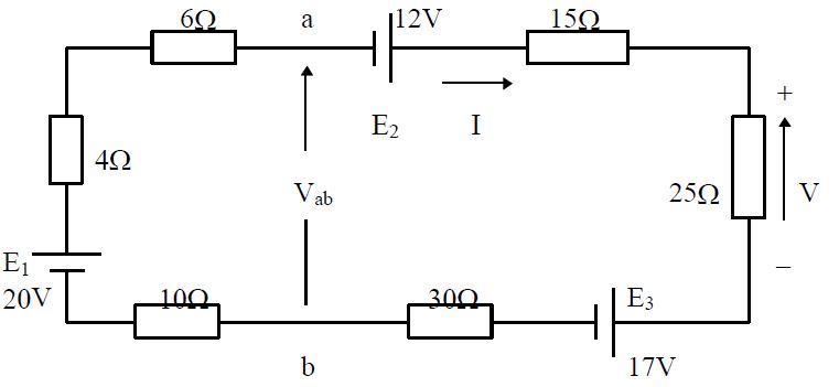
I am trying to solve for the current \$I\$ in the problem below, but (after much googling and reading) I cannot figure out how the current behaves between \$E_1\$ and \$E_3\$.

I discovered that \$-12+15i+25i+17+30i+10i-20+4i+6i=0 \implies i=0.17A\$, which is correct, but I cannot explain why \$30i\$ and \$10i\$ are positive.

Could anyone explain this to me, please.

enter image description here

\$\endgroup\$
3
  • \$\begingroup\$ Because your circuit only has positive resistances. \$\endgroup\$ Commented Aug 22, 2015 at 15:55
  • \$\begingroup\$ Ah, is it really that easy? Thank you so much for taking the time, Vazquez-Abrams! \$\endgroup\$
    – Akitirija
    Commented Aug 22, 2015 at 15:57
  • \$\begingroup\$ It can't possibly be because the current is going the other way, because KCL says it can't. Therefore it must relate to the resistances instead. \$\endgroup\$ Commented Aug 22, 2015 at 15:58

2 Answers 2

0
\$\begingroup\$

This is a simple circuit because all of the components are in series. This means that there is only one current path.

So now you have to find the total voltage accumulated within the circuit as well as the total resistance.

I'm not going to give you the answer but I'll give you a starting point: the battery voltages add together. Starting with the lower-left corner of the circuit, you have battery voltage of: (+20V ) + (+12V) + (-17V). Note carefully the polarity of the batteries.

Given that: what is the total battery voltage?

\$\endgroup\$
1
  • \$\begingroup\$ Hi, thank you, Reid. I already solved these questions. Your comment about "one current path" certainly helps me for future problems, though. I tend to complicate things, and when I saw two poles of same charge on each side of the resistors, I was trying to imagine what the electrons would do, but I couldn't. I still don't really understand what they will do, but if there is only one current path, maybe that's not the point. \$\endgroup\$
    – Akitirija
    Commented Aug 22, 2015 at 17:14
1
\$\begingroup\$

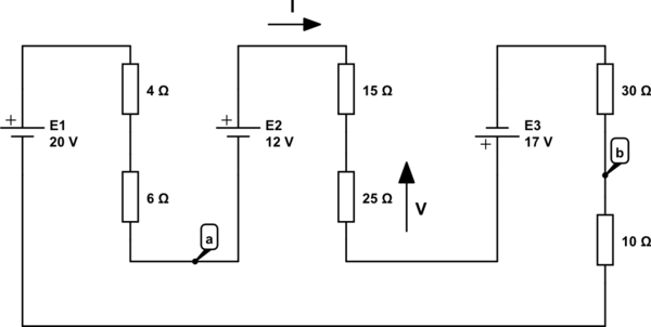
I have redrawn the same circuit in a slightly different way. Hopefully this drawing will give some clarity as to what is going on:

schematic

simulate this circuit – Schematic created using CircuitLab

All of the resistors are oriented so that the current flows through them in the same direction (in the top, out the bottom).

\$\endgroup\$
0

Your Answer

By clicking “Post Your Answer”, you agree to our terms of service and acknowledge you have read our privacy policy.

Not the answer you're looking for? Browse other questions tagged or ask your own question.